


9-11
■ Assembly of the LCD Block
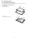
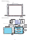
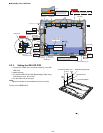
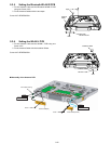
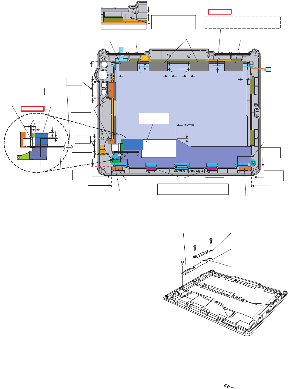
9.2.3. Setting the SW LED PCB
1. Connect the Cable to the connector (CN501) of the SW
LED PCB.
2. Attach the tape.
3. Fix the SW LED PCB and SW Board Stopper Plate using
three Screws <N2>. No1 to No3
4. Put the Cable into the Clamper.
Note:
Tighten the Screws in the numbered order (No1 to No3).
Screws <N2>:DRSB2+5FKL
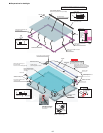
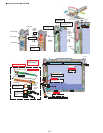
Shield Tape
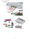
Busterade
LCD Side
Cushion T8
LCD Signal Cable
Pet Tape 1
Pet Tape 1
Pet Tape 1
LCD Block
Shield Tape
LCD Side Cushion T5
LCD Side
Cushion T5
LCD Side Cushion Thin
Caution High
Voltage Label
Shield Tape
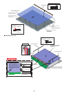
0~1mm
0~3mm
5~6mm
5~6mm 5~6mm
0~3mm
0~3mm
5~6mm
0~1mm
1~3mm
0~1mm
1~3mm
edge standard: +0.5 mm
-
-
Put inside
the rib.
Put inside
the rib.
Match to the edge of the
Connector.
Frame edge
standard
+0.5mm
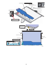
-
Frame edge
standard
+0.5mm
-
-
edge standard: +1mm
Attach to the
undersurface.
Note
Caution to High Voltage
within the rib
Attach the Conductive Cloth
to the Mg side.
(Remove the Release Paper
only of the attaching part.)
When the Cable is close to the edge
(more than 4 mm than the standard position),
ensure that the Cable is not wound in other parts.
Board edge
standard
+0.5mm
-
Board edge
standard
+0.5mm
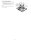
After the liquid crystal block is set, attach LCD
side cushion TS and LCD side cushion thin with
their gluing sides facing downward.
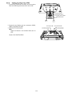
Safety Working
Safety Working
<N2>
<N2>
<N2>
SW LED P.C.B.
SW Board Stopper Plate
Connector(CN501)
Connector(CN500)
No.3
No.1
No.2