


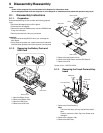
9.2. ReassemblyInstructions
9.2.1. AttentionwhenCF-19seriesisrepaired
ï PleaseexecutewritingBIOSIDwhenyouexchangetheMainBoard.
ïParts(Sheetandrubber)etc.relatedvarioustheConductiveClothandHeatSpreadercannotberecycled.Usenewparts.
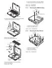
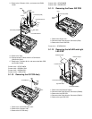
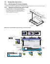
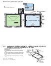
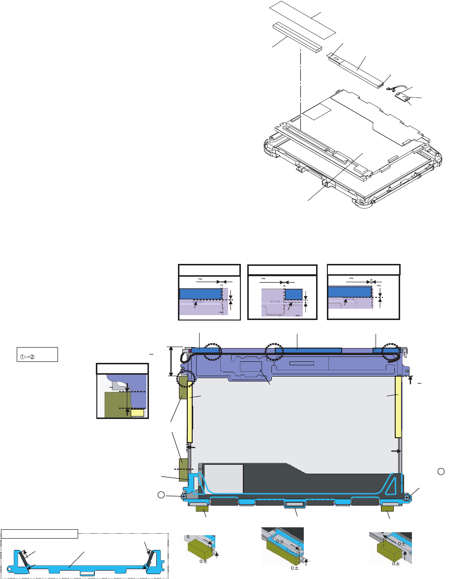
9.2.2. SettinguptheInverterAss'yandLCDUNIT
1. SettheLCDUNITtotheLCDFrontCabinet/TSPanel.
2. SettheTSPCBontheLCDBackDamper,andconnect
the2CablestotheConnectors(CN900andCN901).
3. SettheInverterPCBtotheLCDBackDamper,andcon-
nectthe2CablestotheConnectors.
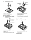
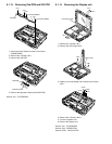
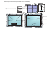
■AssemblyofLCDBackDamper(ApplicableModel:TouchScreenModel)
InverterCase
Tape
InverterPCB
Connector
Connector
LCDUnit
TSPCB
Connector
(CN901)
Connector(CN900)
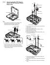
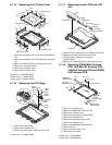
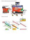
LCDPWBSPACERASSY
AsymmetricShape
Detailof"A"
0 1mm
0 0.5mm
0 1mm
1 1.5mm
0 1mm
0 0.5mm
Detailof"D"
AttachtothesidesurfaceiftheFrame.
(MatchtotheendoftheFramewithin
0to0.5mmatthefarside.)
0.5mm
0
0.5mm
0.5mm
0.5mm
0.5mm
0.5mm
Note:Applytheloadtoattach.20to30N(2.0to3.0Kgf)
Orderoffixing
SpacerSheet
SpacerSheet
LCDPCBSpacer
Detailof"B" Detailof"C"
PasstheCable
undertheprotrusion.
PasstheCable
undertheprotrusion.
PasstheCable
throughthespace.
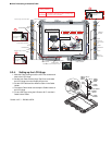
B
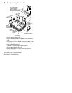
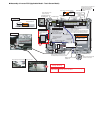
LCD Back Cushion S
LCD Back Cushion L
LCD Back Cushion S
C
D
Remove the Release Paper on
the back side and attach it.
Lengthwise : Match to the LCD Frame.
Crosswise : Match to the middle line.
Holder Sheet
Holder Sheet
Match both Holder Sheet and LCD
Back Cushion S to the right edge
of the frame. (0 to 0.5 mm)
Match both Holder Sheet and LCD
Back Cushion S to the right edge
of the frame. (0 to 0.5 mm)
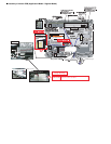
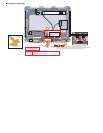
LCD Side Cushion A
LCD PWB Spacer Ass'y
Insert this between LCD
PCB & LCD Frame.
Screw 1
Screw the board and
the Spacer together.
Screw 2
Screw the board and
the Spacer together.
LCD Side Cushion C
LCD Side Cushion D
LCD Side Cushion C
A
33 35mm
2
4mm
0
0.5mm