


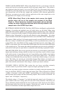

WORD CLOCK SAMPLE RATE: When using Word Clock In as your master clock, this
section tells the driver what the expected word clock input sample rate is. The section is
only displayed when the board is set to use Word Clock In as the master clock source.
From the list, select the sample rate closest to that of the incoming word clock. The sample
rate selected here will be the only sample rate available to the software applications.
Therefore, you must set your audio software application to this same sample rate or else
the application will display an error message.
NOTE: When Word Clock is the master clock source, the digital
monitor mixer will run at the sample rate received at the Word
Clock in. Since frequency response and sample rate are directly
related, the mixer frequency response will be directly related to the
sample rate of the S/PDIF input data.
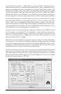
MULTITRACK DRIVER DEVICES: The Delta 1010LT drivers intelligently synchronize the
beginning of recording and playback across all audio devices on the board. When using
application software that is capable of using multiple channels simultaneously, select "Single and
In-Sync" to ensure that all audio channels will begin playback and/or recording at the same time.
Otherwise select "Independent" to allow the audio channels to play independently – this setting
may be desirable if more than one application needs to access the Delta 1010LT simultaneously.
The selection “Multi-card Sync” will remain grayed out until a second Delta PCI card (of which
there are a variety) is installed in the system. When you wish to synchronize two (or more, up
to four) Delta cards, select Multi-card Sync on the second and successive cards. Then, select
S/PDIF as your master clock, and connect the S/PDIF output of the first card to the S/PDIF input
of the second card, etc. This ensures that when the application goes into record or playback, it
waits until all audio ports are open before it commences with recording or playback of audio.
DMA BUFFER SIZES: This section specifies the amount of system memory dedicated to
digital audio buffering. Setting a buffer size that is too small may result in clicks or pops
in the audio stream as some data may be lost. Larger buffers cause slightly more latency
but prevent the pops and clicks that might occur with smaller buffer sizes – the default
settings are recommended but you may desire to tweak these default settings to suit your
tastes. This buffer size must be set in the Delta Control Panel before you launch your
music software. When using ASIO with the Delta 1010LT, set the buffer size in the control
panel, then exit the control panel. After doing so, launch your music software.
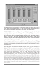
VARIABLE SIGNAL LEVELS: This section has two layers, providing extremely
versatile control of your Delta 1010LT’s input and output operating line levels.
In the first layer there are three selections available for globally setting the operating line
levels for the Delta 1010LT’s analog input and output ports. These selections are labeled
“+4dBu,” “Consumer” (-4dB), and “-10dBV,” represented by sets of radio buttons each for
both the Delta analog inputs and the Delta analog outputs. These sections are labeled “All
Inputs” and “All Outputs,” respectively.
The default setting is “Consumer” for both the input and output levels. Consumer is a
good “middle of the road” setting, and will work well in many situations. The setting you
choose ultimately should match the line level of the source audio device (for the inputs),
and the target audio device (for the outputs). Check the user’s guide for these external
devices for information on their input and/or output line levels.
25