General Description
1-3
Fibre Channel Ports
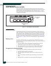
To exit maintenance mode and return to normal operation, momentarily press
and release the Maintenance button to reset the switch module.
Switch Module LEDs
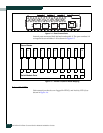
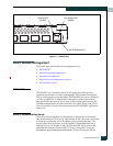
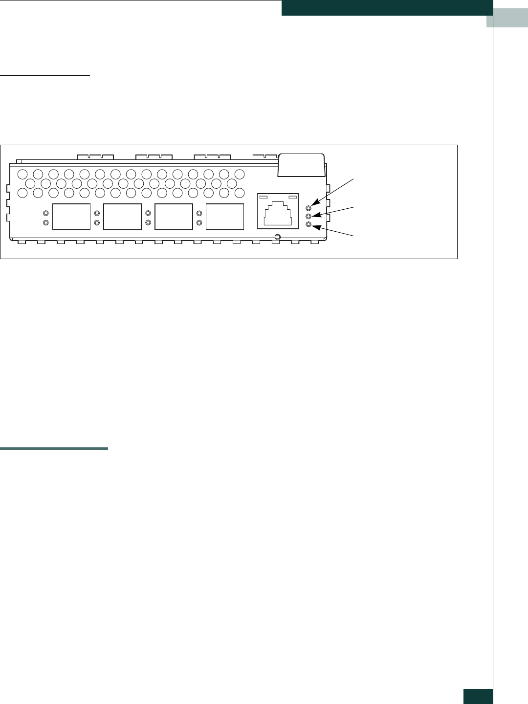
The switch module LEDs shown in Figure 1-3 provide status information
about switch module operation. Refer to “External Port LEDs” on page 1-4 for
information about port LEDs.
Figure 1-3. Switch Module LEDs
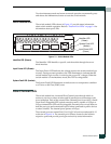
Identifier LED (Green)
The Identifier LED identifies a specific switch module through the server
blade interface.
Input Power LED (Green)
The Input Power LED indicates the voltage status at the switch module logic
circuitry. During normal operation, this LED illuminates to indicate that the
switch module logic circuitry is receiving the proper DC voltages. When the
switch module is in maintenance mode, this LED is extinguished.
System Fault LED (Amber)
The System Fault LED illuminates to indicate an over temperature condition
or a Power on Self Test (POST) error.
Fibre Channel Ports
The switch module has 4 external Fibre Channel ports through which to
connect to devices or other switches and 10 internal ports connecting to the
server midplane. Each of the external Fibre Channel ports is served by a Small
Form-Factor Pluggable (SFP) optical transceiver and is capable of 1-Gbps or
2-Gbps transmission. SFPs are hot-pluggable. External ports can self-discover
both the port type and transmission speed when connected to public devices
or other switches. The internal ports operate at 2-Gbps.
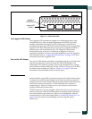
The external ports are named Ext0, Ext1, Ext2, Ext3 and are numbered 10–13
as shown in Figure 1-4. The external port LEDs are located to the left their
respective ports and provide port login and activity status information.
System Fault LED
(Amber)
Identifier LED
(Green)
Input Power LED
(Green)


