


14
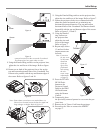
5. Rotate clockwise or
counterclockwise the
Knurled Ring surface
on the front section of
the projector lens to
perform an initial fo-
cus adjustment. Refer
to figures 5 and 6.
Note: Figure 6 is an
example of an
out of focus
image. Do not
be concerned at
this time if the
image doesn’t fill
the screen, is not
centered and/or has geometric distortion.
The next several adjustments will be performed to achieve
the following:
A. Fill the screen with the image.
B. Center the image both horizontally and verti-
cally on the screen.
C. Minimize any horizontal keystone distortion
of the image.
D. Orient the image to be parallel with the top,
bottom and sides of the screen.
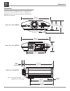
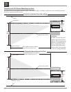
6. Rotate clockwise or counterclockwise the Knurled
Ring surface on
the rear section
of the projector
lens to fill the
screen with the
Crosshatch Test
Pattern. Refer to
figures 5 and 7.
7. Move the entire
projector slightly
to the left or
right to center
the image hori-
zontally on the
screen.
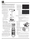
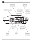
8. Using the LENS
SHIFT Control, located on the Top Control Panel, cen-
ter the image vertically on the screen. Refer to figures
3, 8 and 9.
Note: If the Crosshatch Test Pattern lines change in color
from white to green, the current vertical height of
the projector relative to the screen will not produce
an acceptable image. Reposition either the projec-
tor or the screen vertically so when the image is
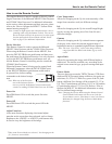
The Initial Setup Section is to assist with minimizing
the possible geometric distortions in the projected image
caused by the physical orientation of the MDLP2 Video
Projector relative to the screen. While there are electronic
adjustments to correct for some of these geometric distor-
tions, the best images will be achieved when minimal elec-
tronic adjustments are used.
After the projector and
screen locations have been
established (refer to the four
previous pages), the next step
is to perform the basic opti-
cal and mechanical orienta-
tion adjustments as follows:
Note: Some installations
might require location
positional adjustments
in addition to and/or in
place of the projector’s
built-in adjustments.
1. Connect the projector to
a live AC Outlet.
2. Remove the protective
cover from the projector
lens.
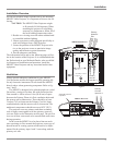
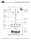
3. The Red LED to the
left of the STANDBY/
ON Push-button lights
to indicate the MDLP2 is in Standby
mode. To Switch ON the MDLP2,
press the STANDBY/ON Push-button
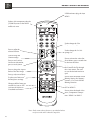
on the Projector Control Panel or the
PROJector ON Push-button using the
Remote Control. The Green LED to
the right of the STANDBY/ON Push-
button lights to indicate the MDLP2
is ON. Refer to figures 3 and 4.
Note: It is normal for the projector
lamp warm up period to last
about a minute before an image
appears on the screen.
4. Press the PATTERN Push-button on
the Control Panel or the Remote Con-
trol. Refer to figures 3 and 4.
The Crosshatch Test Pattern (Horizon-
tal and Vertical White Lines on a Black
Background) will appear on the screen
and will be used during the following
steps. Refer to figures 5 and 6.
Initial Setup
Figure 5
Figure 6
LARGER
SMALLER
IMAGE SIZE
IMAGE FOCUS
Figure 7
Figure 4
Figure 3
2