


17
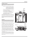
How to Connect the MDLP2
How to Connect the MDLP2
The MDLP2 has the ability to automatically switch power
On/Off to McIntosh Components via the Power Control
and Trigger Connections. The Data Port Connections allow
for the remote operation of the MDLP2 from other McIn-
tosh Components. With an external sensor connected to
the MDLP2, remote control operation is possible when the
MDLP2 is located in an enclosure.
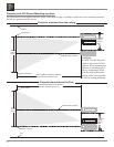
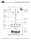
The connection instructions below, together with the
AP1000/MDLP2/VP1000 Input and Control Connection
Diagrams located on the separate folded sheet “Mc2A and
Mc2B”, are an example of a typical audio/video system.
Your system may vary from this; however, the actual com-
ponents would be connected in a similar manner.
For additional information refer to “Connector and
Cable Information” on page 6.
Note: With the addition of a McIntosh Power Controller
connected to the MDLP2, AC Power Switching can
be provided to components such as a motorized
projection screen. Contact your McIntosh Dealer for
additional information.
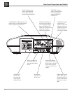
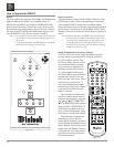
Power Control Connections:
1. Connect a Control Cable from the MDLP2 POWER
CONTROL IN Jack to the Power Control Out A Jack
on the McIntosh VP1000 Video Processor.
If the MDLP2 is connected to a McIntosh Audio/Video
Control Center MX136, MX135, MX120, MX119, MX134
or MX132 (MX Series) add the following connection:
2. Connect a Control Cable from the MDLP2 POWER
CONTROL IN A Jack to the McIntosh MX Series
Power Control Zone A Out Jack.
Data Control Connections:
When the MDLP2 is connected to the McIntosh VP1000
Video Processor, no Data Port connection is necessary.
If the MDLP2 is connected to a McIntosh Audio/Video
Control Center MX136, MX135, MX120, MX119, MX134
or MX132 (MX Series) add the following connection:
3. Connect a Control Cable from the MDLP2 DATA IN
Jack to the McIntosh MX Series SUM A Data Port
Jack.
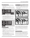
Video Connections:
When the MDLP2 is connected to the McIntosh VP1000
Video Processor, add the following connections. If there is
no VP1000, proceed to step 6.
4. Connect a Video Cable from the MDLP2 Y1, PB1 and
PR1 COMPONENT VIDEO Input Jacks to the McIn-
tosh VP1000 Component Video MON A Jacks.
5. Connect a Video Cable from the MDLP2 HDMI 1
Input Jack to the McIntosh VP1000 HDMI MON A
Output Jack.
If the MDLP2 is connected to a McIntosh Audio/Video
Control Center MX136, MX135, MX120, MX119, or
MX134 (MX Series) add the following connection:
6. Connect a Video Cable from the MDLP2 Y1, PB1 and
PR1 COMPONENT VIDEO Input Jacks to the McIn-
tosh MX Series Component Video MON A Jacks.
7. Connect a Video Cable from the MDLP2 HDMI 1
Input Jack to the McIntosh MX Series HDMI MON A
Output Jack.
Note: Only the MX136 and MX120 Audio/Video Con-
trol Centers will have a HDMI MON A Jack.
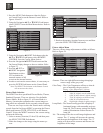
AC Power Cord Connections:
8. Connect the MDLP2 AC Power Cord to a live AC
outlet.
9. Connect the remaining components’ AC Power Cords.