


6
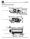
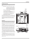
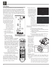
Power Control Connectors
The MDLP2 Power Control Output Jacks send and Power
Control Input Jacks receive Power On/Off Signals when
connected to McIntosh and other non-
McIntosh Components. A 1/8 inch
stereo mini phone plug is used for con-
nection to the Power Control Input and
Outputs on the MDLP2.
Note: The Data and Power Control Connecting Cable is avail-
able from the McIntosh Parts Department:
Data and Power Control Cable Part No. 170-202
Six foot, shielded 2 conductor, with 1/8 inch stereo mini
phone plugs on each end.
Data Port Connectors
The MDLP2 Data In Port receives
Remote Control Signals from other
McIntosh Components. A 1/8 inch
stereo mini phone plug is used for
connection. The IR Ports also use a
1/8 inch stereo mini phone plug and
allow the connection of other brand
IR Receivers to the MDLP2.
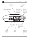
RS232 DB9 Connector Pin Layout
1. N/C 6. N/C
2. Data Out (TXD) 7. N/C
3. Data In (RXD) 8. N/C
4. N/C 9. N/C
5. Gnd.
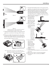
Connector and Cable Information
Power
Control
Ground
N/C
Data
Signal
N/C
Data
Ground
IR Data
Control
Ground
N/C