


14 Installation Guide
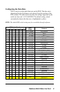
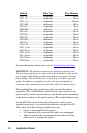
Model # Fiber Type Max Distance
O211-40 ........................... singlemode ...................................40 km
O211-70 ........................... singlemode ...................................70 km
O211-1A........................... singlemode .................................100 km
O221-M5.......................... multimode ....................................500 m
O221-10 ........................... singlemode ...................................10 km
O280-M2.......................... multimode ......................................2 km
O281-40 ........................... singlemode ...................................40 km
O281-80 ........................... singlemode ...................................80 km
O283-20 ........................... singlemode ...................................20 km
O292-M5.......................... multimode ....................................500 m
O293-20 ........................... singlemode ...................................20 km
O2A3-10 .......................... singlemode ...................................10 km
O311-10-xx ...................... singlemode ...................................10 km
O383-20-xx ...................... singlemode ...................................20 km
O411-80-xx ...................... singlemode ...................................80 km
O413-40-xx ...................... singlemode ...................................40 km
O413-80-xx ...................... singlemode ...................................80 km
O483-80-xx ...................... singlemode ...................................80 km
For more information about optics, refer to Technical Specifications.
IMPORTANT: The distances noted are for reference purposes only.
The most important factor to achieve the desired distance is the optical
power budget. Metrobility specifications indicate the typical transmit
power budget. The actual distance is a function of the fiber type and
quality, the number and quality of splices, the type and quality of
connectors, the transmission loss, and other physical characteristics.
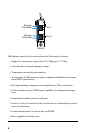
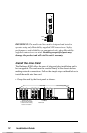
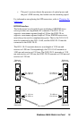
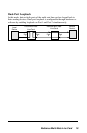
When making fiber optic connections, make sure that the optical
transmitter (TX) on the Radiance multi-rate line card connects to the
optical receiver on the connected device, and that the optical transmitter
on the device connects to the optical receiver (RX) on the Radiance card.
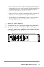
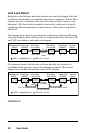
Use the SD LEDs on the front panel of the card to verify correct
segment connectivity. As you insert the cable into each port, the SD
LED will be lit if the following conditions are met:
• Power is being applied to the chassis.
• All connections are secure and the cables are undamaged.
• There is an active device connected to the other end of the
cable, and it is sending idle signals.