


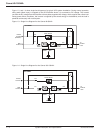
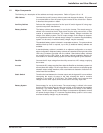
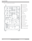
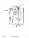

Figure 1-3, and 1-4 show single-line diagrams of a typical UPS system installation. During normal operation,
utility power (Main Input) is supplied to the UPS Rectifier where it is converted to DC voltage. The Inverter
converts the DC voltage from the Rectifier to three-phase regulated AC voltage, which supplies the critical load.
During power failure conditions, the Inverter is supplied by the stored energy in the batteries, and the load is
powered continuously with no disruption.
Figure 1-3: Single Line Diagram for the Comet 40-80kVA.
Figure 1-4: Single Line Diagram for the Comet 100-150kVA.
Comet 40-150kVA
System Description and Specifications1 — 2 86-160310-00 E00
TO
CRITICAL
LOAD
MAIN
AC INPUT
QF1
OUTPUT
FUSES
UPS CABINET
K3N
INVERTER
RECTIFIER
INPUT
FUSES
STATIC SWITCH
BYPASS
AC INPUT
(OPTIONAL)
KA1
BATTERY
KA2
SR1
BATTERY
CABINET
TO
CRITICAL
LOAD
MAIN
AC INPUT
QF1
OUTPUT
FUSES
UPS CABINET
K3N
INVERTER
RECTIFIER
INPUT
FUSES
STATIC SWITCH
BYPASS
AC INPUT
KA1
BATTERY
KA2
SR1
BATTERY
CABINET