


Installation and User Manual
Figures
figure description . . . . . . . . . . . . . . . . . . . . . . . . . . . . . . . . . . . . . . . . . . . . . . . . .page
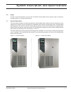
1-1: Comet 40-80kVA. . . . . . . . . . . . . . . . . . . . . . . . . . . . . . . . . . . . . . . . . . . . . . . . .
1-2: Comet 100-150kVA . . . . . . . . . . . . . . . . . . . . . . . . . . . . . . . . . . . . . . . . .1 — 1
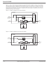
1-3: Single Line Diagram for the Comet 40-80kVA . . . . . . . . . . . . . . . . . . . . .1 — 2
1-4: Single Line Diagram for the Comet 100-150kVA . . . . . . . . . . . . . . . . . . .1 — 2
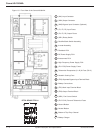
1-5: Front View of the Comet 40-80kVA . . . . . . . . . . . . . . . . . . . . . . . . . . . . .1 — 4
1-6: Rear View of the Comet 40-80kVA . . . . . . . . . . . . . . . . . . . . . . . . . . . . .1 — 5
1-7: Front View of the Comet 100-150kVA . . . . . . . . . . . . . . . . . . . . . . . . . . .1 — 6
1-8: Front View of Communications Components for
the Comet 100-150kVA . . . . . . . . . . . . . . . . . . . . . . . . . . . . . . . . . . . . . .1 — 7
1-9: Pinouts on the DB15 Connector . . . . . . . . . . . . . . . . . . . . . . . . . . . . . . .1 — 10
2-1: The Comet 100-150kVA on Pallet . . . . . . . . . . . . . . . . . . . . . . . . . . . . . .2 — 2
3-1: Power Flow, For Normal Operation . . . . . . . . . . . . . . . . . . . . . . . . . . . . .3 — 1
3-2: Power Flow, For On Battery Operation . . . . . . . . . . . . . . . . . . . . . . . . . .3 — 1
3-3: Power Flow, For Bypass Operation . . . . . . . . . . . . . . . . . . . . . . . . . . . . .3 — 2
3-4: Comet Front Panel GUI, Controls and Indicators . . . . . . . . . . . . . . . . . .3 — 3
3-5: Output Current Overload Curve . . . . . . . . . . . . . . . . . . . . . . . . . . . . . . . .3 — 7
3-6: Output Power Overload Curve . . . . . . . . . . . . . . . . . . . . . . . . . . . . . . . . .3 — 7
Tables
table description . . . . . . . . . . . . . . . . . . . . . . . . . . . . . . . . . . . . . . . . . . . . . . . . .page
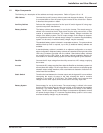
1-1: Comet 40-150kVA Specifications . . . . . . . . . . . . . . . . . . . . . . . . . . . . . . .1 — 8
1-2: UPS Manager Dry Contact Interface . . . . . . . . . . . . . . . . . . . . . . . . . . .1 — 10
2-1: Recommended upstream protective device sizing * . . . . . . . . . . . . . . . .2 — 3
MGE Warranty & Proprietary Rights for Three Phase Products
MGE Standard Three Phase Warranty
Proprietary Rights Statement
Warranty and Product Registration
User Information
Product Information
Warranty Extension (Warranty+)
Customer Care Center - Three Phase Products
Technical Support and Product Services
Who to Contact
Scheduling Field Service Engineer Support
Return Policy for Repair of Three Phase Products (RGA)
Glossary
Reorder Form
Contents c iii86-160310-00 E00