


Installation and User Manual
NOTES:
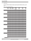
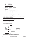
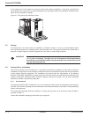
1. Total width, weight, and heat loss are for system line-up excluding battery cabinets.
2. Data does not include battery data; refer to the installation drawings supplied with your equipment.
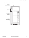
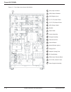
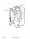
Consult the installation drawings provided with your equipment.
1.3.1 AC Input Ratings
Voltage 480 VAC, + 12%, -15%
Frequency 60 Hz ± 4%
Phases 3 Ø (phase sequence must be A, B, C, clockwise)
Wires 3 wires plus ground (480-480 VAC only)
Power factor Approximately 0.98 at full load
Current (on UPS/ on BYP
ASS) @ 480 VAC
40kVA 50kVA 65kVA 80kVA 100kVA 125kVA 150kVA
43A/48A 54A/60A 70A/78A 86A/96A 109A/120A 134A/150A 160A/180A
1.3.2 AC Output Ratings
Voltage (inverter only) 480 ± 1% VAC (steady-state conditions)
480 ± 5% VAC (transient conditions from 0% to 100% or 100% to 0%)
Frequency 60 Hz ± 0.1% (free-running)
Phases 3 Ø (phase sequence must be A, B, C, clockwise)
Wires 3 wires plus ground (480-480 VAC only)
Power factor 0.8
Current @ 480 VAC
40kVA 50kVA 65kVA 80kVA 100kVA 125kVA 150kVA
48A 60A 78A 96A 120A 150A 180A
Total harmonic
distortion (THD) <2% (linear load)
<3% (for 100% non-linear load with a crest factor of less than 3.0)
Dynamic regulation ± 1% for balanced load
± 2.5% for 100% unbalanced load
Dynamic response ± 5% for 100% step load change
Overload 105% - 110% of rated current for 10 minutes
>110% - 130% of rated current for 1 minute
>130% - 150% of rated current for 10 seconds
>150% of rated current for 0.15 seconds
1.3.3 DC Ratings
Battery voltage (25° C) float: 490 Vdc
nominal: 432 Vdc
minimum: 360 Vdc
Maximum Current at cut-of
f voltage
40kVA 50kVA 65kVA 80kVA 100kVA 125kVA 150kVA
96 ADC 120 ADC 154 ADC 189 ADC 235 ADC 294 ADC 353 ADC
System Description and Specifications 1 — 986-160310-00 E00