


Installation and User Manual
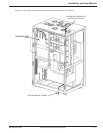
1.2 Major Components
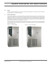
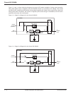
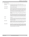
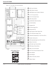
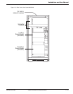
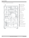
The following is a description of the cabinets and major components. Refer to Figures 1-5 to 1-8.
UPS Cabinet Converts the input AC power to direct current and charges the battery. DC power
is converted back to clean AC power by the inverter for the critical load. Section
3 describes the operation in detail.
Auxiliary Cabinet Performs the voltage conversion for the input AC and/or bypass AC using step-
up and/or step-down transformers.
Battery Cabinet The battery cabinet stores energy for use by the Inverter. The stored energy is
utilized in the event that the AC input power from the utility source fails, or falls
outside of acceptable tolerances. The internal Battery Charger maintains the
charge of the battery system. The DC output voltage of the charger is tempera-
ture regulated to ensure an optimal charge voltage. If a customer supplied battery
system is to be used, an external battery charger may be necessary.
The standard battery system is housed in a separate enclosure. For systems where
additional back-up time is required, up to two (2) additional battery cabinets are
available.
A standard battery cabinet is available in an adjacent configuration or a stand-
alone configuration. Adjacent battery cabinets are attached to the right side of the
UPS using c-brackets provided with the cabinet. Stand-alone battery cabinets
are remote from the UPS. Refer to the battery cabinet installation drawing for
more details. An external battery system can also be supplied by the customer.
Rectifier Converts the AC input voltage from the utility source into a DC voltage, supplying
the Inverter.
Inverter Converts the DC voltage supplied from either the Rectifier or the battery system into
a three-phase AC voltage. An AC output filter is used to achieve a computer-grade
sinewave output voltage waveform, with a total harmonic distortion of less than 2%
under linear-load conditions.
Static Switch Transfers the load between the Inverter output and the bypass AC source without
interrupting the supply of power to the load, allowing the load to continue
operation in the event of a UPS fault. The Static Switch circuit assures that
voltage from the UPS output cannot be fed back to the utility input lines.
Battery System Stores energy for use by the Inverter. The stored energy is utilized in the event
that the AC input power from the utility source fails, or falls outside of acceptable
tolerances. The internal Battery Charger maintains the charge of the battery
system. The DC output voltage of the charger is temperature regulated to ensure
an optimal charge voltage. If a customer supplied battery system is to be used,
an external battery charger may be necessary.
System Description and Specifications 1 — 386-160310-00 E00