


Installation and User Manual
2.6.4 AC Output
The connections to be made are the three phases, and ground cables from the load source to the UPS. The
output cables are terminated at the Output Terminal Block (TB2) for 40-80kVA, and the output busbars for 100-
150kVA.
Load cables must be run separately from all other cables (power supply or computer-system interconnection
cables). They should not pass near interference-emitting equipment or sensitive loads.
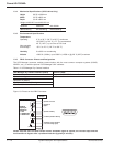
2.6.5 Battery
The connections to be made are the positive, negative, and ground cables from the battery cabinet to the UPS.
These are terminated at the appropriate connections in the UPS cabinet (see Figures 2-3 and 2-4). Additionally,
control wires and temperature sensors in the battery cabinet must be terminated. Refer to the battery cabinet
installation drawings for more details.
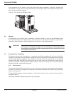
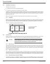
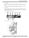
Figure 2-3: Connections for Comet 40-80kVA UPS.
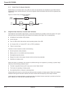
Figure 2-4: Connections for Comet 100-150kVA UPS.
Installation 2 — 586-160310-00 E00
Separate Bypass
Input Terminal
Block TB3
(Optional)
Battery
Connections
Main Input
Terminal Block
TB1
Output
Terminal Block
TB2
Fan Control
Switch
SR2
Fan and
Teleservice Fuses
FU7-FU12
Ground Busbar Neutral Busbar
OUTPUT
BYPASS
INPUT
A4
B4
OPT
C4
A3
B3
C3
A5
B5
C5
+
-
BATT.