


2.5 Installation Procedures
The steps to be followed are:
◗ Placement of the UPS and associated equipment.
◗ Connection of input power, output power, and control cables.
Installation of UPS equipment must be handled by skilled technicians and electrician's familiar with the special
requirements of high-energy electrical equipment. We strongly recommend contracting MGE Customer Support
Services for start-up of the installed Comet UPS system. Do not allow unqualified personnel to handle or
operate the Comet UPS.
Refer to the installation drawings for proper placement and connections of auxiliary cabinets.
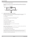
2.5.1 Placement
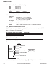
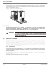
Move the Comet UPS, battery cabinets (if any), and auxiliary cabinets (if any), to their final location (see Figure
2-2). For cabinets installed adjacent to each other, alignment is critical to properly install the mechanical and
cable interconnections. Allow at least 36 inches clearance above all cabinets for maintenance and cooling.
Figure 2-2: Placement of UPS and other Cabinets.
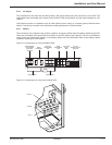
2.6 Connections
Electrical connections and cabinet interconnection will vary depending upon the configuration of your Comet
UPS system. Refer to Figures 2-3 & 2-4 and to the installation drawings supplied with your equipment.
CAUTION Before making any electrical connections, verify that all battery disconnect
circuit breaker (QF1) are in the “off” position. Customer-supplied upstream
protective devices and distribution circuits should be OFF.
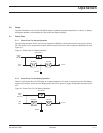
2.6.1 Main AC Input
The connections to be made are the three phases, and ground cables from the utility AC power source to the
UPS. The main AC input cables are terminated at the "Main Input" Terminal Block (TB1) for 40-80kVA and the
input busbars for 100-150kVA. Complete wiring instructions for your installation are provided on the installation
drawings supplied with the equipment.
2.6.2 Bypass AC Input (Optional)
The connections to be made are the three phases, and ground cables from the bypass AC input power source
to the UPS. The bypass AC input cables are terminated at the "Bypass Input" Terminal Block (TB3) for 40-80kVA
and the bypass busbars for 100-150kVA. This option provides a separate AC input source for bypass operation.
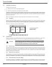
2.6.3 Remote Emergency Power Off (REPO)
The control connections are available for "Remote Emergency Power Off" (REPO) through a customer-supplied
normally closed pushbutton. With REPO connected, the jumper on the "REPO" terminal blocks must be removed.
Comet 40-150kVA
Installation2 — 4 86-160310-00 E00
AUX
CAB
UPS
BATTERY
CABINET(s)
36" recommended
For side and rear clearances,
refer to each cabinet's
installation drawing