Installation and User Manual
1 — 386-173010-00 A00
1.4 Galaxy 4000 Standard Cabinets
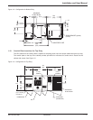
The Galaxy 4000 individual cabinet dimensions are:
◗ UPS cabinet: 72.1in (1831mm) H x 33.5in (851mm) W x 35.6in (904mm) D.
◗ External battery cabinet: 72.1in (1831mm) H x 26.5in (673mm) W x 33.5in (851mm) D OR –
◗ External battery cabinet: 72.1in (1831mm) H x 33.5in (851mm) W x 33.5in (851mm) D.
◗ Distribution cabinet: 72.1in (1831mm) H x 19.5in (495mm) W x 33.5in (851mm) D.
The UPS cabinet is designed to provide for top and bottom entry of the utility power feed. An output voltage of
208VAC is standard with the Galaxy 4000 and does not require any additional cabinetry. The complete list of
additional cabinets that could be included with your Galaxy 4000 system are: external maintenance bypass wall
cabinet, external battery cabinet, and distribution cabinet.
The external battery cabinets are provided in two different cabinet sizes depending upon the battery type selected.
Up to four battery cabinets may be provided. The cabinets may be installed adjacent to the UPS or remotely and
are designed for top and bottom entry. The distribution cabinet provides a 42 pole panelboard, with an optional
submain circuit breaker. The cabinet is designed for top and bottom entry.
1.5 Preparation for Operation
Several items must be considered when preparing the Galaxy 4000 UPS system for operation.
First The UPS cabinet and its auxiliary cabinets must be arranged in the required configuration to insure that
the interconnection cables are located in the correct adjacent cabinets.
Second The cabinets must be in a location that provides for proper air flow and heat rejection.
Third The room in which the Galaxy 4000 UPS system is located must maintain environmental conditions within
recommended tolerances.
Forth All electrical connections must utilize the top or bottom conduit entries provided.
The following sections discuss these items in more detail.
1.6 Cabinet Placement
The complete UPS system may consist of one to three cabinets depending on the options selected. The UPS
cabinet allows system options to be selected based on the application. When facing the Galaxy 4000 UPS from the
front, the standard arrangement provides for any external batteries to be located on the right hand side, and the
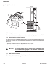
distribution cabinet to be located on the left hand side of the UPS. Refer to Figure 1-3 for cabinet placement.
1.7 Heat Rejection and Air Flow
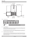
The Galaxy 4000 UPS cabinets generate heat and exhaust air through the top portion of its enclosures. Air intake
is through the bottom and front of the cabinet. All other cabinets are convection cooled. To assist you in planning for
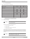
your HVAC needs, heat rejection data is provided in Table 1-1. The cabinet airflow and recommended top clearance
are provided in Figure 1-3. The Galaxy 4000 is intended for use in an environment where control of temperature
and humidity is provided.
Introduction


