Installation and User Manual
◗ Battery temperature does not stay within ±10°C from the starting temperature point.
◗ Communication fault.
◗ Input current 0 amps or > 100% load current.
◗ Rectifier or inverter overload.
◗ Mains 1 or Mains 2 failure.
In case the BPI cannot be done, a simplified autonometer will be used. This autonometer will start and display
backup time when the batteries are 100% charged. Because the calculation used is more simplified than the one
used for calculating backup time using a BPI, these will be less accurate. Therefore it is preferable to use the BPI
whenever possible. This provides an option for example, when less than 15% load or cannot run a BPI.
NOTE Any of the displayed items Ï be examined further by using the soft key with the
double arrows to select the item of interest and then pressing the soft key with the
magnifying glass.
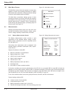
3.4.2 Power Measurements Screen
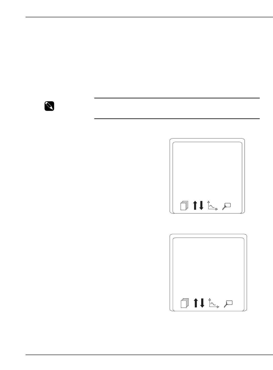
The Power Measurements screen displays the load
power on each phase in KVA and in KW. Additionally,
the AC "normal" (AC N) source is shown with the KVA.
See Figure 3-7.
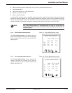
3.4.3 Current Measurements Screen
The Current Measurements screen displays the
current on the load, AC “normal” (AC N), and AC
“bypass” (AC BP) on each of the three phases and
neutral. See Figure 3-8.
Display Panel 3 — 586-173010-00 A00
Figure 3-7: Power Measurements screen.
Figure 3-8: Current Measurements screen.
Current measurements
Load AC N AC BP
I1 5 A 5 A 0 A
I2 5 A 6 A 0 A
I3 5 A 5 A 0 A
IN 7 A 0 A
Power measurements
Load Load AC N
kVA kW kVA
Ph1 0.6 0.5 1.1
Ph2 0.6 0.5 1.1
Ph3 0.6 0.5 1.0


