


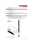

2. Installation
Safety Precautions
This section contains important safety and regulatory information that should be reviewed before installation
and use. For input and output current ratings, see Power Ratings in Technical Specifications.
Only for installation and use in a
Restricted Access Location in
accordance with the following
installation and use instructions.
Seulement pour l’installation et
l’utilisation dans une Zone Interdite
conformément aux installations et
l’utilisation des indications suivants.
Nur zur Installation und Verwendung in
einem Sicherheitsbereich gemäß den
folgenden Installations- und
Verwendungsanleitungen.
This equipment is designed to be
installed on a dedicated circuit.
Cet équipement est conçu à être
installé sur un circuit spécialisé.
Diese Ausrüstung ist zur Installation in
einem festen Stromkreis vorgesehen.
Dedicated branch circuit must have
circuit breaker or fuse protection; 3-
phase/multi-pole dedicated branch
circuits must have circuit breaker or fuse
protection for each phase/pole located
together. PDUs have been designed
without a master circuit breaker or fuse
to avoid becoming a single point of
failure. It is the customer’s responsibility
to provide adequate protection for the
dedicated branch power circuit.
Protection should not exceed the Total
Input Rating of the PDU and must meet
all applicable local, state and federal
codes and regulations.
Le circuit de dérivation spécialisé doit
être équipé de disjoncteurs ou de
fusibles ;
Lorsqu'ils sont triphasés ou
multipolaires, ils doivent être équipés
de disjoncteurs ou de fusibles sur
chaque phase ou pôle. Les PDU ont
été conçus sans disjoncteur ou fusible
principal afin de ne pas constituer le
seul point de rupture. Le client est
seul responsable de la protection des
circuits électriques de dérivation
spécialisés. Cette protection ne doit
pas excéder la consommation totale
en entrée du PDU et doit être
conforme aux normes et à la
réglementation locales, d'état et
fédérales.
Der als Standleitung verwendete
Zweigstromkreis muss mit einem
Überlastschalter bzw. einer Sicherung
ausgestattet sein; bei Standleitungs-
Zweigstromkreisen mit 3
Phasen/mehreren Polen müssen
zusammengehörige Phasen/Pole
individuell durch einen Überlastschalter
bzw. eine Sicherung geschützt sein. In
PDUs ist kein Haupt-Überlastschalter
bzw. keine Hauptsicherung installiert.
Dadurch wird ausgeschlossen, dass die
PDU als alleinige Schwachstelle in
Frage kommt. Es liegt in der
Verantwortung des Kunden, den als
Standleitung verwendeten
Zweigstromkreis durch entsprechende
Schutzmaßnahmen vor Überlastung zu
schützen. Der Wert für den
Überlastschutz darf nicht über dem Wert
für die Eingangsstromstärke der PDU
liegen und muss geltenden örtlichen und
staatlichen Bestimmungen entsprechen.
The plug on the power supply cord shall
be installed near the equipment and
shall be easily accessible.
La prise sur le cordon d’alimentation
sera installée près de l’équipement et
sera facilement disponible.
Der Stecker des Netzkabels muss in der
Nähe der Ausrüstung installiert werden
und leicht zugänglich sein.
Always disconnect the power supply
cord before opening to avoid electrical
shock.
Toujours déconnecter le cordon
d’alimentation avant d’ouvrir pour
éviter un choque électrique.
Ziehen Sie vor dem Öffnen immer das
Netzkabel heraus, um die Gefahr eines
elektrischen Schlags zu vermeiden.
WARNING! High leakage current!
Earth connection is essential before
connecting supply!
ATTENTION ! Haut fuite très
possible ! Une connection de masse
est essentielle avant de connecter
l’alimentation !
ACHTUNG! Hoher Ableitstrom! Ein
Erdungsanschluss ist vor dem
Einschalten der Stromzufuhr
erforderlich!
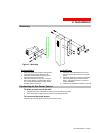
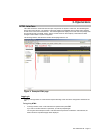
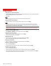
Installing the Power Input Retention Bracket
For Switched PDUs with a total maximum output <30A, it may be
necessary to install the power input retention bracket prior to mounting
the Switched PDU within the rack.
To install the power input retention bracket:
1. Remove the two screws attaching the IEC 60320 C19 inlet to the
enclosure.
2. Assemble and attach the retention bracket to the enclosure as
shown.
Figure 2. Retention Bracket assembly
Page 6 - 301-0399-3 Rev B.