


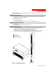

2. Installation
Connecting Devices
To avoid the possibility of noise due to arcing:
1. Keep the device’s on/off switch in the off position until after it is plugged into the outlet.
2. Connect devices to the outlets.
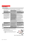
On 230V units, install a retention clip for each outlet; Pull the prongs out slightly and insert them into holes
on the sides, then insert the device’s power cord and snap the clip over the cord.
NOTE:
1. MGE UPS SYSTEMS recommends even distribution of attached devices across the all available outlets to
avoid exceeding the outlet, quad or octet ratings limitations. See Power Ratings in Technical
Specifications for more information.
2. The outlet retention clips provided with 230V units are designed for use with MGE UPS SYSTEMS’s IEC
60320/C13 to IEC 60320/C14 cable and may not properly fit 3
rd
party cables.
Always disconnect the power supply cord before opening to avoid electrical shock.
Afin d’éviter les chocs électriques, débranchez le cable électrique avant d’ouvrir.
Immer Netzleitung auskuppeln vor den Aufmachen um elektrischen Schlag zu vermeiden.
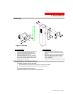
Connecting the Sensors
The AmpMeter PDU may be equipped with two mini RJ11 T/H ports for attachment of the included
Temperature/Humidity sensor. Attach the mini RJ11 plug of the sensor(s) to the appropriate T/H port if
applicable.
Connecting to the Unit (Remote Monitoring Units Only)
Serial (RS232) port
AmpMeter PDU models may be equipped with an RJ45 Serial RS-232 port for attachment to a PC or networked
terminal server using the supplied RJ45 to RJ45 crossover cable and RJ45 to DB9F serial port adapter as
required. See Data Connections in Technical Specifications for more information on the Serial RS-232 port.
Ethernet port
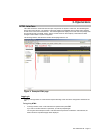
AmpMeter PDU models may be equipped with an RJ45 10/100Base-T Ethernet port for attachment to an
existing network. This connection allows access via Telnet, Secure Shell (SSH) or a common web browser.
The unit configured with the following network defaults to allow unit configuration out-of-the-box through either
Telnet/SSH or via a web browser:
• IP address: 192.168.1.254
• Subnet Mask: 255.255.255.0
• Gateway: 192.168.1.1
The local PC network connection must be configured as noted below:
NOTE: Contact your system administrator for instructions in reconfiguring the network connection.
Reconfiguration of your network connection may require a restart to take effect.
• IP address: 192.168.1.x (where x is 2-253)
• Subnet Mask: 255.255.255.0
Page 8 - 301-0399-3 Rev B.