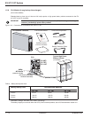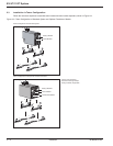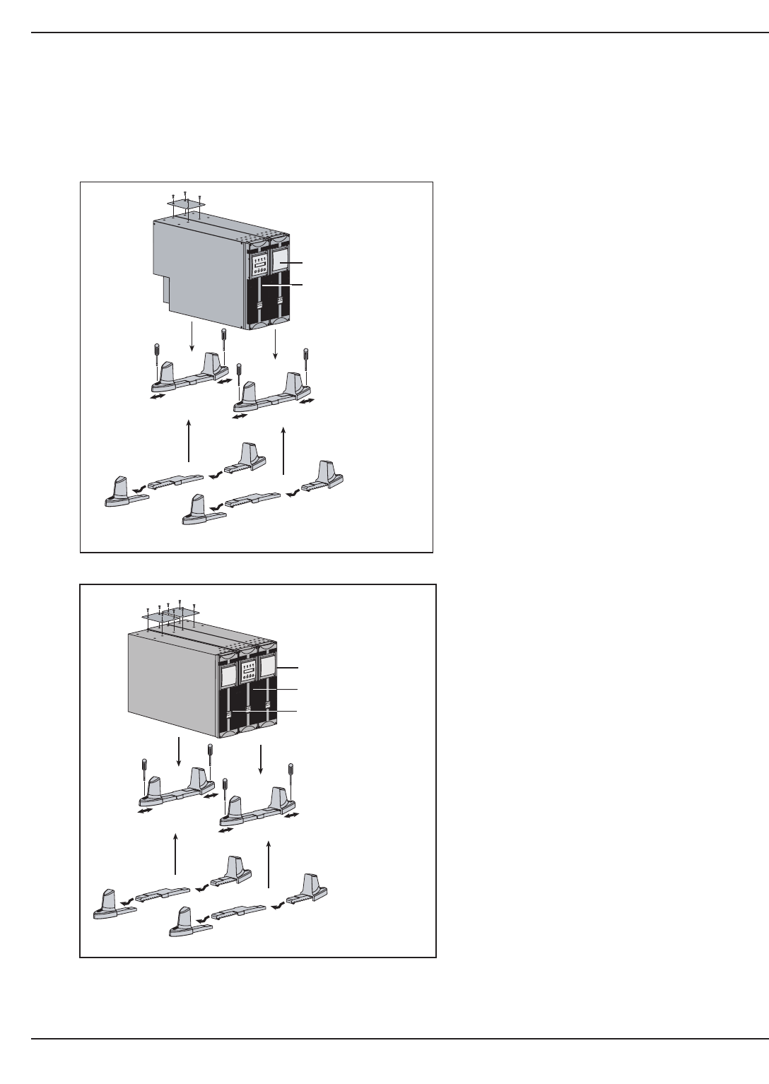
2.3 Installation in Tower Configuration
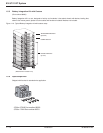
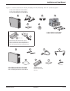
Follow the numerical sequence to assemble tower stands and tower stand expanders, shown in Figure 2-2.
Figure 2-2: Tower Configuration of Standard System and Optional Transformer Module.
EX 5/7/11 RT System
Installation2 — 4 86-86000-00 A01
w
w
w
.
m
g
e
u
p
s
.
c
o
m
w
w
w
.
m
g
e
u
p
s
.c
o
m
E
X
B
R
T
E
X
1
1
R
T
O
F
F
O
N
w
w
w
.
m
g
e
u
ps
.
c
o
m
Tower Configuration with Optional Transformer Module
Tower Configuration with Standard System
Use the same procedure
for tower mounting multiple
battery modules, if applicable.
w
w
w
.
m
g
e
u
p
s
.
c
o
m
w
w
w
.
m
g
e
u
p
s
.
c
o
m
E
X
B
R
T
E
X
1
1
R
T
O
F
F
O
N
Transformer Module
Battery Modules
Power Module
Battery Module
1
1
2
2
4
4
4
4
3
3
5
1
1
2
2
4
4
4
4
3
3
5
Power Module


