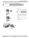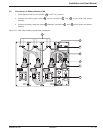
2.7.4 Remote Emergency Power Off (REPO) Communication Port
The end user is responsible for the installation of an emergency power off function. Installation must be carried out
in compliance with local code regulations.
To shutdown the entire system completely in case of emergency:
Disconnect the AC input to the power module.
Turn off the circuit breaker of the battery module connecting to the power module.
Turn off the circuit breaker of the subsequent battery modules, if applicable.
All these steps above should be performed via a single device.
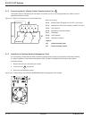
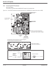
To simplify the last two steps above, the power module provides an RJ-45 connector on the back panel, called
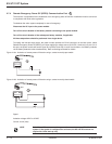
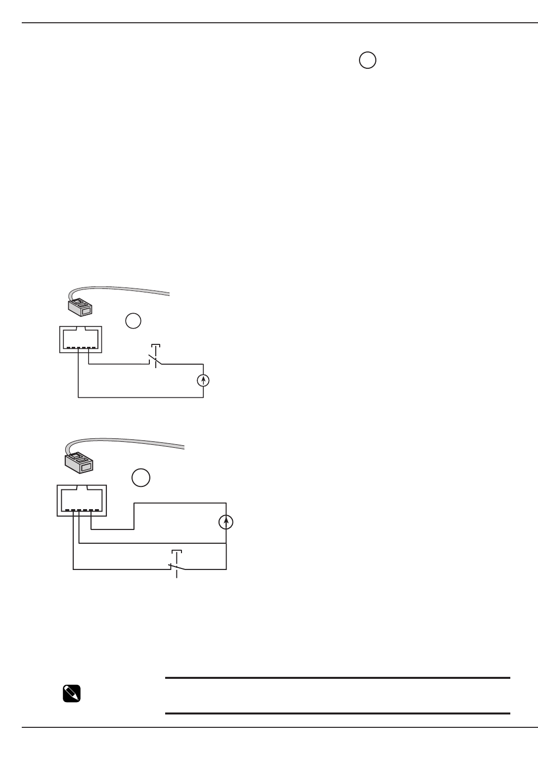
Remote Emergency Power Off (REPO) port. Upon applying a voltage source (5-27VDC, 10mA max.) to pins 2, 4 of
this port, the power module will send a signal to trip off the shunt trip on each circuit breaker of all battery modules
via the battery detection cable simultaneously. Refer to the diagram below for details.
Figure 2-10a: Activation of remote power off function using a contact normally open switch.
Figure 2-10b: Activation of remote power off function using a contact normally closed switch.
Signal:
Activation voltage: 5VDC to 27VDC
Current 10 mA (max)
NOTE Both AC and DC sources must be present for normal start-up of EX 5/7/11RT
system. If the system is configured for cold start, the AC and DC sources are
required for initial start-up only.
3
EX 5/7/11 RT System
Installation2 — 12 86-86000-00 A01
RJ11
5432
1
6
3
5432
1
6
RJ11
3


