


Page 20 - 34007724EN/AA
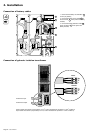
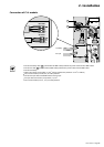
2. Installation
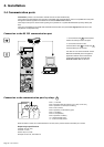
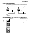
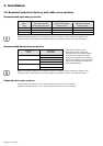
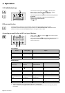
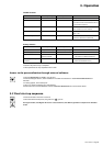
2.6 Required protective devices and cable cross-sections
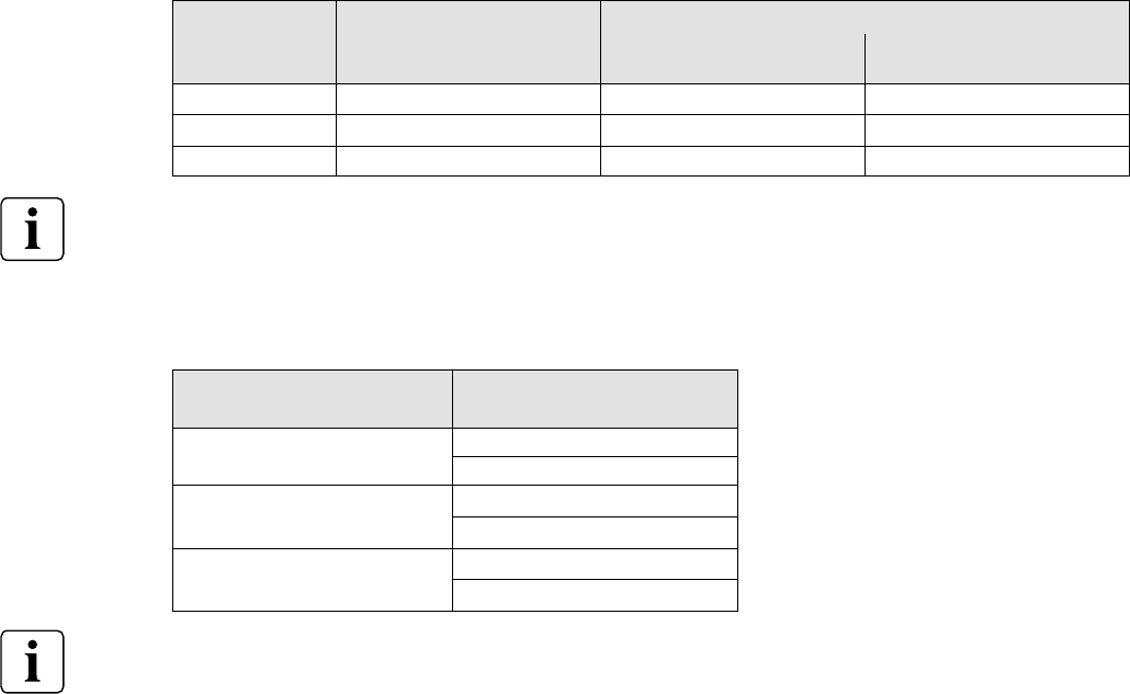
Recommended upstream protection
Recommended downstream protection
The indicated protection ensures
discrimination for each output circuit
downstream of the UPS, whether supplied
by the Normal or the Bypass AC source.
If these recommendations are not followed,
protection discrimination is not achieved and
may result in a potential power interruption
to the connected devices.
Required cable cross-sections
◗ Terminal-block cable capacity: 10 mm
2
, solid or stranded wire (maximum 13 mm
2
or AWG 6).
◗ Capacity for earthing conductor: 10 mm
2
, solid or stranded wire (maximum 13 mm
2
or AWG 6).
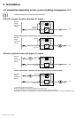
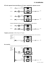
Note: see the simplified diagrams in the appendix for common or separate AC inputs, indicating the positions of the
protection devices, the characteristics of the internal UPS fuses and UPS line currents under overload conditions.
Note: see the simplified diagrams in the appendix for common or separate AC inputs, indicating the positions of the
protection devices, the characteristics of the internal UPS fuses and UPS line currents under overload conditions.
Downstream
circuit breaker
Z curve - 10A
C curve - 4A
Z curve - 10A
C curve - 4A
Z curve - 10A
C curve - 6A
UPS power
rating
5 kVA
7 kVA
11 kVA
Common AC inputs
Upstream circuit-breaker
Normal / Bypass AC sources
D curve - 40A
D curve - 40A
D curve - 63A
UPS
power
rating
5 kVA
7 kVA
11 kVA
Upstream circuit-breaker
Normal AC source
C curve - 32A
C curve - 32A
C curve - 63A
Separate AC inputs
Upstream circuit-breaker
Bypass AC source
D curve - 40A
D curve - 40A
D curve - 63A