


34007724EN/AA - Page 3
Contents
1. Presentation
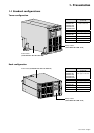
1.1 Standard configurations .............................................................................................................. 5
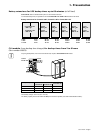
Tower configuration ......................................................................................................................... 5
Rack configuration .......................................................................................................................... 5
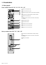
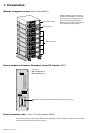
1.2 Rear panels.................................................................................................................................... 6
Power module Comet EX 5 RT / EX 7 RT / EX 11 RT .................................................................... 6
Battery module Comet EXB 7 RT / EXB 11 RT ............................................................................... 6
1.3 Display and control panel ............................................................................................................ 7
1.4 Options .......................................................................................................................................... 7
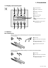
Rack mounting kits.......................................................................................................................... 7
Transformer for galvanic isolation or earthing arrangement change .............................................. 8
Battery extensions for UPS backup times up to 60 minutes ........................................................... 9
CLA module (Long backup time charger) for backup times from 2 to 8 hours ................................ 9
Modules integration system .......................................................................................................... 10
Battery module with Remote Emergency Power Off function (REPO) ......................................... 10
Battery extension cable (1,8 m / 6 ft) ............................................................................................ 10
2. Installation
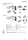
2.1 Unpacking and parts check ....................................................................................................... 11
Power module ............................................................................................................................... 11
Battery module .............................................................................................................................. 11
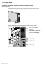
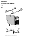
2.2 Installation in tower configuration ............................................................................................ 12
2.3 Installation in rack configuration .............................................................................................. 13
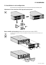
Adjustment of the orientation of the logo and control panels ........................................................ 13
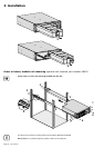
Battery module rack mounting (optional rail required) .................................................................. 13
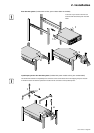
Power or battery module rack mounting (optional rail required) ................................................... 14
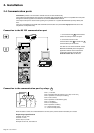
2.4 Communication ports ................................................................................................................. 16
Connection to the RS232 communication port ............................................................................. 16
Connection to the communications port by relays ........................................................................ 16
Remote Power Off communication port ........................................................................................ 17
Installation of communication cards (optional, standard with the Network Pack version)............. 17
2.5 Installation depending on the system earthing arrangement (SEA) ...................................... 18
UPS with common Normal and Bypass AC inputs........................................................................ 18
UPS with separate Normal and Bypass AC inputs ....................................................................... 18
UPS with separate Normal and Bypass AC inputs, supplied by separate sources....................... 19
Frequency converter (without Bypass AC input) ........................................................................... 19
Hot standby ................................................................................................................................... 19
2.6 Required protective devices and cable cross-sections .......................................................... 20
Recommended upstream protection ............................................................................................. 20
Recommended downstream protection ........................................................................................ 20
Required cable cross-section........................................................................................................ 20
2.7 Connections of input/output power cables .............................................................................. 21
UPS with common Normal and Bypass AC sources..................................................................... 21
UPS with separate Normal and Bypass AC sources .................................................................... 22
Frequency converter ..................................................................................................................... 23
Connection of battery cables ........................................................................................................ 24
Connection of galvanic isolation transformer ................................................................................ 24
Connection of CLA module ........................................................................................................... 25