


Page 22 - 34007724EN/AA
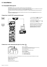
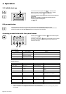
Card Settings
RS232 Download
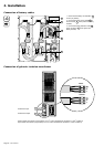
66074
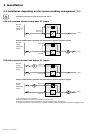
UPS
data
Reset
100 10
1 2
ON
ETHERNET
IP=
MAC=00E0D8FF855E
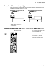
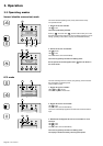
N
O
R
M
A
L
φ
R
e
c
t
i
f
i
e
r
I
n
p
u
t
L
2
L
1
L
1
B
y
p
a
s
s
I
n
p
u
t
N
2
L
2
N
1
L
3
O
u
t
p
u
t
N
L
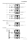
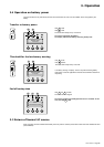
R
e
c
t
if
i
e
r
I
n
p
u
t
L
2
L
1
L
1
B
y
p
a
s
s
I
n
p
u
t
N
2
L
2
N
1
L
3
O
u
t
p
u
t
N
L
R
e
c
t
i
f
i
e
r
I
n
p
u
t
L
2
L
1
L
1
B
y
p
a
s
s
I
n
p
u
t
N
2
L
2
N
1
L
3
O
u
t
p
u
t
N
L
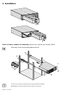
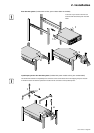
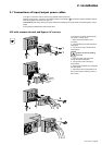
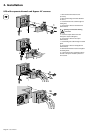
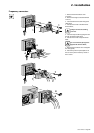
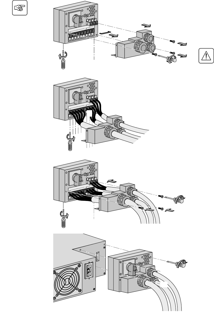
1 - Remove the terminal block cover
(5 screws),
2 - Remove the bridge connected between
L2 and L1,
3 - Insert the Normal AC cable through the
cable gland,
4 - Connect the 5 wires to the Normal AC
terminal block,
Always connect the earthing
wire first.
5 - Insert the Output cable to the load
through the Output cable gland,
6 - Connect the 3 wires to the output
terminal block,
7 - Insert the Bypass cable through the cable
gland,
8 - Connect the 3 wires to the Bypass AC
terminal block,
9 - Refit the terminal block cover and tighten
the cable glands,
10 - Secure the junction Input/Output box to
the rear of the power module by means of
the 3 screws.
UPS with separate Normal and Bypass AC sources
2. Installation
1
5
2
4
3
9
6
7
1
1
1
9
9
9
10
1
8
9
10
10