


34007724EN/AA - Page 33
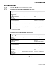
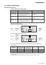
BY
PASS
NORMAL
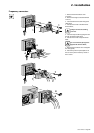
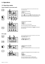
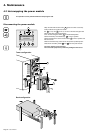
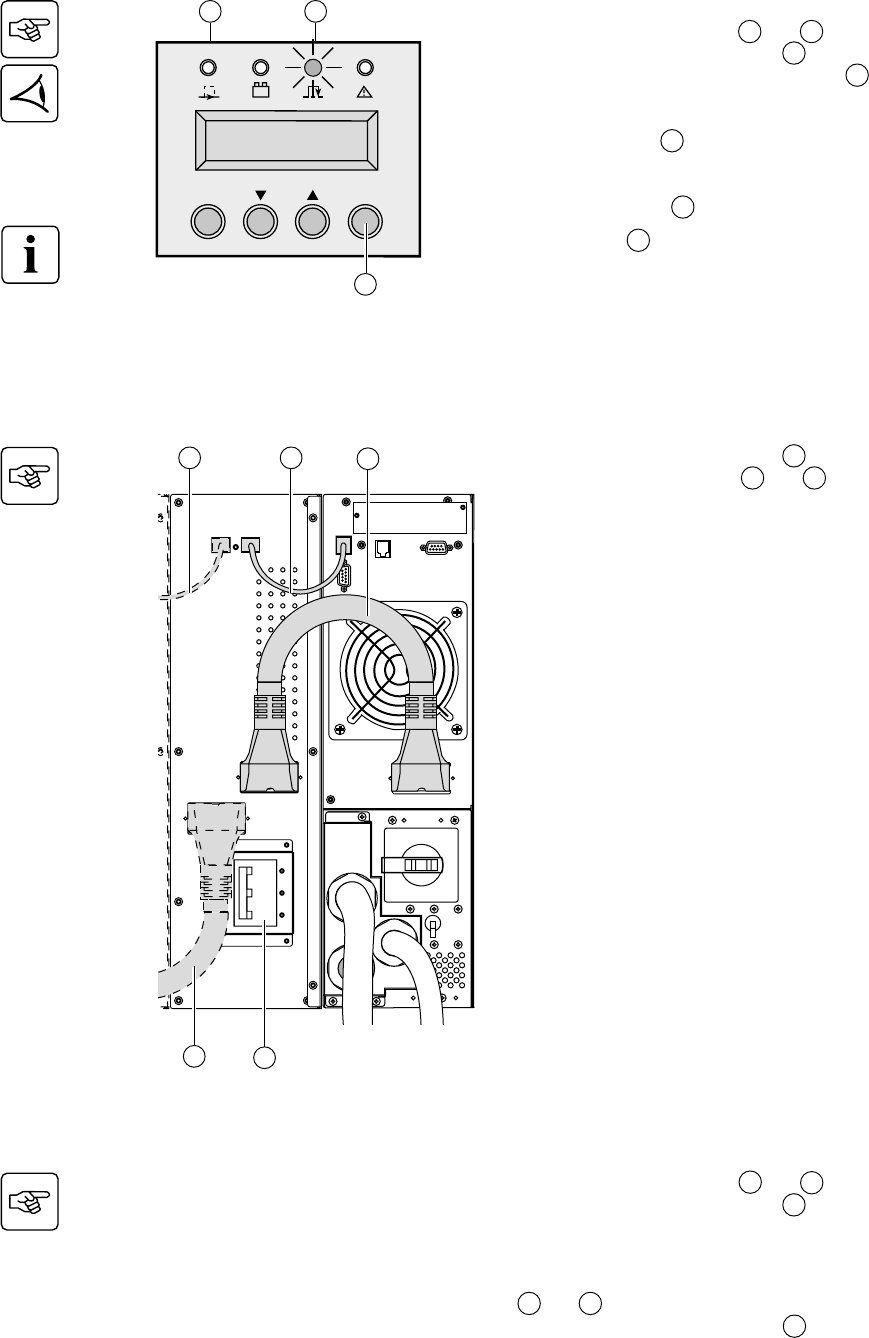
4.3 Hot-swapping the battery module
Disconnecting the battery module
◗ Switch the battery circuit breaker(s) 12 to the "0" position.
◗ Disconnect the battery cables 28 and 29 from the power module.
The battery module can be replaced. The connected equipment is
powered by the UPS.
It is also possible to replace battery trays instead of battery module.
Contact your nearest after sales support service.
To remove battery trays:
◗ First, switch the battery circuit breaker(s) to the "0" position.
◗ See section 2.3 and follow instructions to remove battery trays.
12
28
29
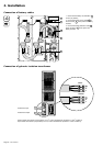
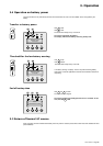
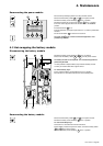
Reconnecting the battery module
◗ Reconnect the battery cables 28 and 29 to the power module.
◗ Switch the battery circuit breaker(s) 12 to the "I" position.
To reconnect battery trays:
See section 2.3 and follow the reverse instructions.
◗ When battery module front panel is closed, connect the battery cables
28 and 29 to the power module.
◗ Switch the battery circuit breaker(s) 12 to the "I" position.
29
28
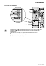
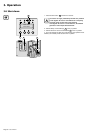
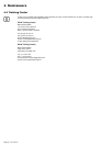
Reconnecting the power module
◗ Secure the Input/Output junction box using the three screws.
◗ Reconnect the battery cables 28 and 29 to the power module.
◗ Switch the battery circuit breaker(s) 12 to the "I" position.
◗ Switch the Normal AC source circuit-breaker 9 to the "I" position.
◗ Turn the manual bypass switch from the BYPASS to the NORMAL
position.
◗ Check that the led 15 is on.
◗ Follow initial start up sequence (see section 3.1) in order to personalize
the UPS.
◗ Push the ON button 21 for more than 3 seconds.
The green led 13 is on, and the connected equipment is now
protected by the UPS.
15
OFF
ON
13
21
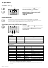
4. Maintenance
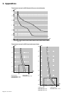
LOAD LEVEL
4 kW / 5 kVA