


Page 24 - 34007724EN/AA
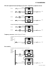
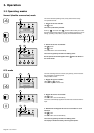
BY
PASS
NORMAL
N
L
N
L
OUTPUT
INPUT
2. Installation
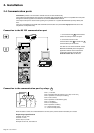
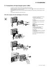
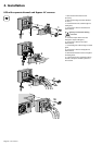
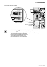
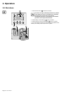
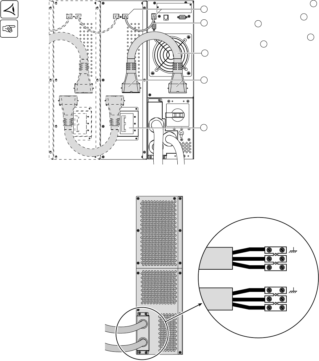
Connection of battery cables
1 - Check that the battery circuit breaker 12
is OFF ("0" position),
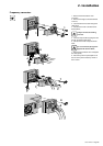
2 - Connect the battery power cable 28 to
the connectors 6 of the power and battery
modules,
3 - Connect the battery detection cable 29
to the connectors 4 of the power and
battery modules,
28
6
4
29
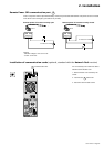
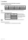
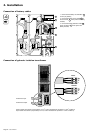
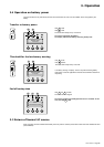
Connection of galvanic isolation transformer
◗ Output cable cross-section (not provided): 10 mm
2
, solid or stranded wire (maximum 13 mm
2
or AWG 6).
◗ Input cable cross-section (not provided): 10 mm
2
, solid or stranded wire (maximum 13 mm
2
or AWG 6).
Transformer Input
Transformer Output
12