


- 5 -
Depending on the data traffic, the Link LED will begin to flash, indicating that the
camera is receiving/sending data from/to the network.
3. Internal MIC
The built-in omni-directional microphone allows the camera to receive sound and
voice.
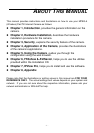
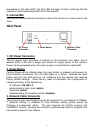
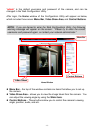
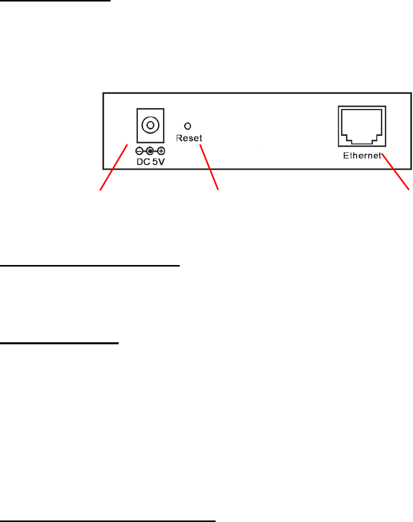
Rear Panel
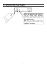
1. DC Power Connector
The DC power input connector is located on the camera’s rear panel, and is
labeled DC5V 2.5A with a single jack socket to supply power to the camera.
Power will be generated when the power supply is connected to a wall outlet.
2. Reset Button
Factory Reset will be initiated when the reset button is pressed continuously for
three seconds; meanwhile, the Link LED lights up or blinks. Release the reset
button and the Link LED will turn off, indicating that the camera has restored
factory default settings. When factory reset is completed, the configuration of
camera will return to the defaults as:
- IP address: 192.168.1.2
- Administrator’s login name: admin
- Password: admin
- Wireless status (for wireless model): disabled
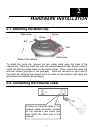
3. Network Cable Connector
The camera’s rear panel features an RJ-45 connector for connections to 10Base-
T Ethernet cabling or 100Base-TX Fast Ethernet cabling (which should be
Category 5 twisted-pair cable). The port supports the N-Way protocol and
“AutoMDIX” function, allowing the camera to automatically detect or negotiate the
transmission speed of the network.
3. Network Cable
Connector
1. DC Power
Connector
2. Reset Button