


March 10, 2009 Dolphin Interconnect Solutions 16
www.dolphinics.com
Note:
Cables should be strain relieved or strapped to a cabinet/rack to ensure additional
reliability.
Note: Cables should be connected according to the configuration of your DSE4XM product.
The configuration is documented on the configuration sheet included with your
product. The standard StorExpress configuration is single server. Multiple server
configurations require additional DXH510 adapter cards and cables, which may be
purchased through http://www.dolphinics.com
.
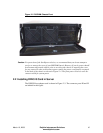
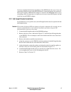
2.4 Powering up the DSE4XM
1. Connect main power (100-240VAC) to the DSE4XM chassis using the provided
AC power cord or a regionally appropriate AC power cord to the DSE4XM chassis
power connector, which is located on the back of the chassis, as shown in Figure 2–
1. The AC power cord provided by Dolphin is a Northern American 3- prong plug.
A different power cord, with the appropriate power prongs, is required for other
geographies that don’t support the North American standard. The chassis accepts
any IEC 320 EN60320 C13 connector and the power supply provided with the
DXE410 accepts any voltage from 100V to 240V at a frequency of 50-60Hz.
Auxiliary power is supplied to the DSE4XM when AC power is connected.
2. An AC power switch for each power supply unit is located on the back of the chas-
sis near the power connector, as shown in Figure 2–1. These switches must be
placed in the on position to provide full AC power to the chassis.
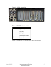
3. A DC power switch is provided in the front of the chassis, as shown in Figure 2–2.
This switch can be used to manually fully power up the chassis.
The DSE4XM chassis provides automatic remote power-on capabilities. Toggling
the front power button is not necessary to fully power to the chassis. As long as AC
power is switch on, the DSE4XM will fully power up when the server (or first
server) is powered on.
– When fully powered, the DSE4XM will go through a self test. You will observe
that for 0.5 seconds the P0 and P1 LEDs on the Uplink slots will turn green.
Then for 0.5 seconds, the P0 and P1 LEDs turn yellow. If the servers connected
to the DSE4XM are powered down, or if the connectors are not cabled, then the
LEDs will turn off.
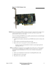
4. Power-on the server that contains the DXH510. If not already powered, after server
power is turned on, the DSE4XM will come on automatically. This is indicated by
the following:
– Chassis fans will turn on
– The Uplink Slot P0 and P1 LEDs will transition from yellow to off and then
green for connected ports, as described in the previous step.
5. Check the P0 and P1 LEDs for both the DXH510 and the DSE4XM Uplink slot(s)
– For a x8 or a single x4 connection, the P0 LED should be illuminated
– For two x4 connections, both the P0 and P1 LEDs should be illuminated