Printer Panel 1
– 37 –
4581-7777-01
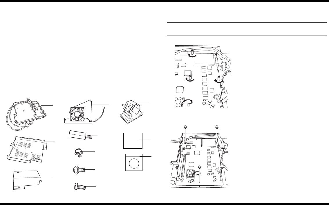
13.3 Checking the Contents of the Enclosed Interface Kit
Before starting to set up, check that the following accessories are included with this unit.
1. Controller mounting plate ........................................................................................ 1
2. Controller cover .......................................................................................................1
3. Power cord cover .....................................................................................................1
4. Fan assembly ..........................................................................................................1
5. Shoulder screws ...................................................................................................... 3
6. Screws (6 for installing the circuit board and 3 for installing the fan) ....................... 9
7. Screws
(5 for temporary mounting, 11 for installing the controller cover and
2 for installing the controller) ................................................................................. 18
8. Screws (for installing the power cord cover) ............................................................ 2
9. CKN clamp .............................................................................................................. 2
10.Installation Guide* ................................................................................................... 1
11.CD-ROM* ................................................................................................................ 1
*:Cannot be used with the CF2002/CF3102 printer.
13.4 Installing the Interface Kit and Printer Controller Circuit
Board
NOTE
A Phillips screwdriver is needed in order to install the printer controller circuit board.
C4025U901AA
C4025U902AA
C4025U903AA
C4025U904AA
C4025U905AA
C4025U906AA
C4025U908AA
C4025U907AA
C4025U909AA
1
2
3
4
5
6
7
8
9
Cd_1
10
11
1. Attach the controller circuit board to the con
-
troller mounting plate using the three shoul
-
der screws (5) by tightening them in th
e
following order:
➀
,
➁
, then
➂
.
C4025u912AA
➀
➁
➂
2. Secure the controller circuit board with th
e
six screws (6) for installing the circuit board.
C4025u910AA


