


App - 14
Appendix 5 Program for Refresh when Using Multiple Local Modules
Appendix 5.1 System configuration and setting conditions
APPENDICES
Appendix 5.1 System configuration and setting conditions
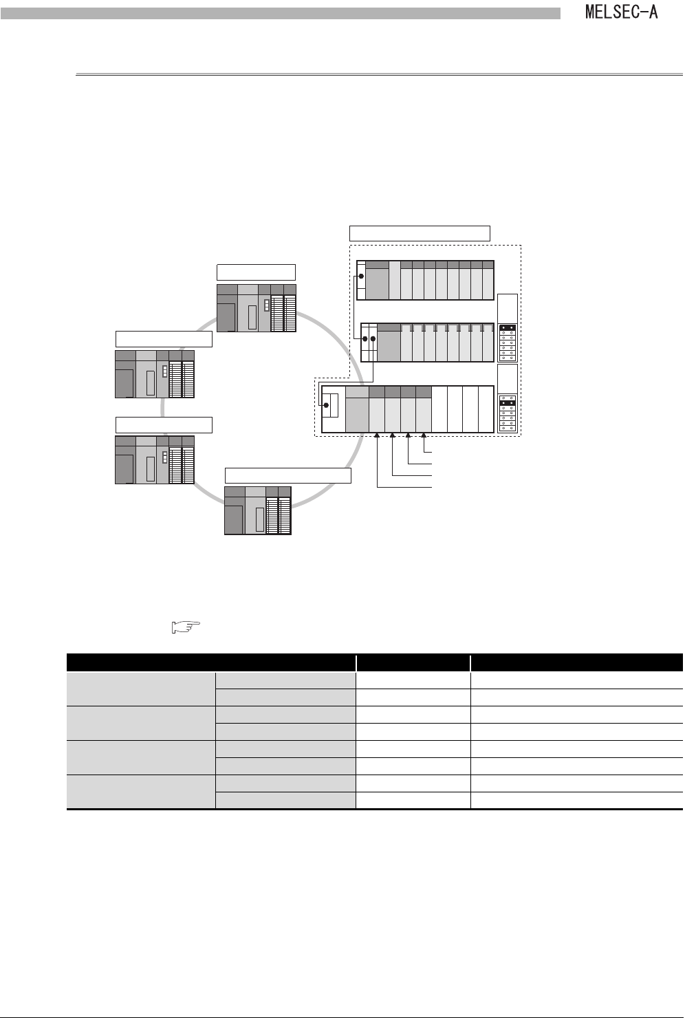
Program examples given here are based on the following system configuration and setting
conditions.
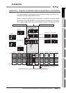
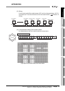
(1) System configuration
The following figure shows that a 32-point module is installed to each slot. (The points
for an empty slot is 16.)
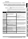
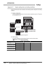
(2) Switch setting
Set the DIP switches on the front face of the link module as shown below.
( Section 5.3 Part Names and Settings)
Figure App.2 System configuration
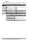
Table App.5 Switch setting
Item Number (Set value) Description
Master station
Station No. setting switch 00 Station No.0
Mode setting switch 0 Online (with automatic return function)
Local stations No.1 and No.2
Station No. setting switch 01 to 02 Station No.1 to No.2
Mode setting switch 0 Online (with automatic return function)
Remote I/O station No.3
Station No. setting switch 03 Station No.3
Mode setting switch 0 Online (with automatic return function)
Local stations No.4 to No.7
Station No. setting switch 04 to 07 Station No.4 to No.7
Mode setting switch 0 Online (with automatic return function)
MELSECNET II
(Q38B)
A1SJ71AP23Q (L5 station)
Master station
Local station No.1
Local station No.2
Local stations No.4 to No.7
(QA1S68B)
00 to 1F
20 to 3F
60 to 7F
80 to 9F
A0 to BF
C0 to DF
(Q68B)
Extension
1st
Extension
2nd
Remote I/O station No.3
A1SJ71AP23Q (L6 station)
A1SJ71AP23Q (L7 station)
A1SJ71AP23Q (L4 station)
40 to 5F
E0 to FF
100 to 11F
120 to 13F
160 to 17F
180 to 19F
1A0 to 1BF
1C0 to 1DF
140 to 15F
1E0 to 1FF
2B0 to 2BF
2A0 to 2AF
290 to 29F
280 to 28F
260 to 27F
240 to 25F
220 to 23F
200 to 21F