


3
SPECIFICATIONS
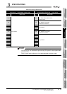
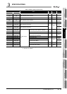
3.6 Details of Buffer Memory
3.6.3 Refresh information table
3 - 20
1
OVERVIEW
2
SYSTEM
CONFIGURATION
3
SPECIFICATIONS
4
FUNCTIONS
5
PREPARATORY
PROCEDURES BEFORE
OPERATION
6
LINK DATA SEND/
RECEIVE PROCESSING
AND PROCESSING TIME
7
PROGRAMMING
8
TROUBLESHOOTING
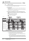
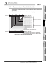
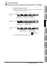
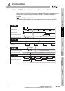
(1) Each station send range of B/W
When a local module is a local station in the second tier (L1 station), each station
send range of B/W is stored as follows:
Figure 3.7 Each station send range of B/W for refresh information table
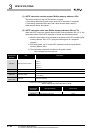
100 200 300 380
(Empty)
FFF
ML1 L3
Readable range
Writable range
B/W 0
L2
Other station send range (1)
Start number: 0000
H
Number of points: 0100
H
Host station send range
Start number: 0100
H
Number of points: 0100
H
Other station send range (2)
Start number: 0200
H
Number of points: 0180
H
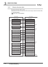
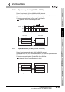
100 200 300 380 FFF
ML1 L3
B/W 0
L2
Other station send range (1)
Start number: 0100
H
Number of points: 0280
H
Host station send range
Start number: 0000
H
Number of points: 0100
H
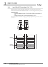
100 200 280 380 FFF
ML1L3
B/W 0
L2
Other station send range (1)
Start number: 0000
H
Number of points: 0280
H
Host station send range
Start number: 0280
H
Number of points: 0100
H
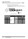
Link parameter assignment
example (1)
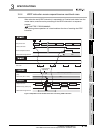
Link parameter assignment
example (2)
Link parameter assignment
example (3)
(Empty)
(Empty)