


5
PREPARATORY PROCEDURES BEFORE
OPERATION
5.5 Self-diagnostic Test
5.5.3 Forward loop test/reverse loop test
5 - 20
1
OVERVIEW
2
SYSTEM
CONFIGURATION
3
SPECIFICATIONS
4
FUNCTIONS
5
PREPARATORY
PROCEDURES BEFORE
OPERATION
6
LINK DATA SEND/
RECEIVE PROCESSING
AND PROCESSING TIME
7
PROGRAMMING
8
TROUBLESHOOTING
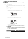
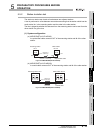
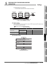
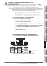
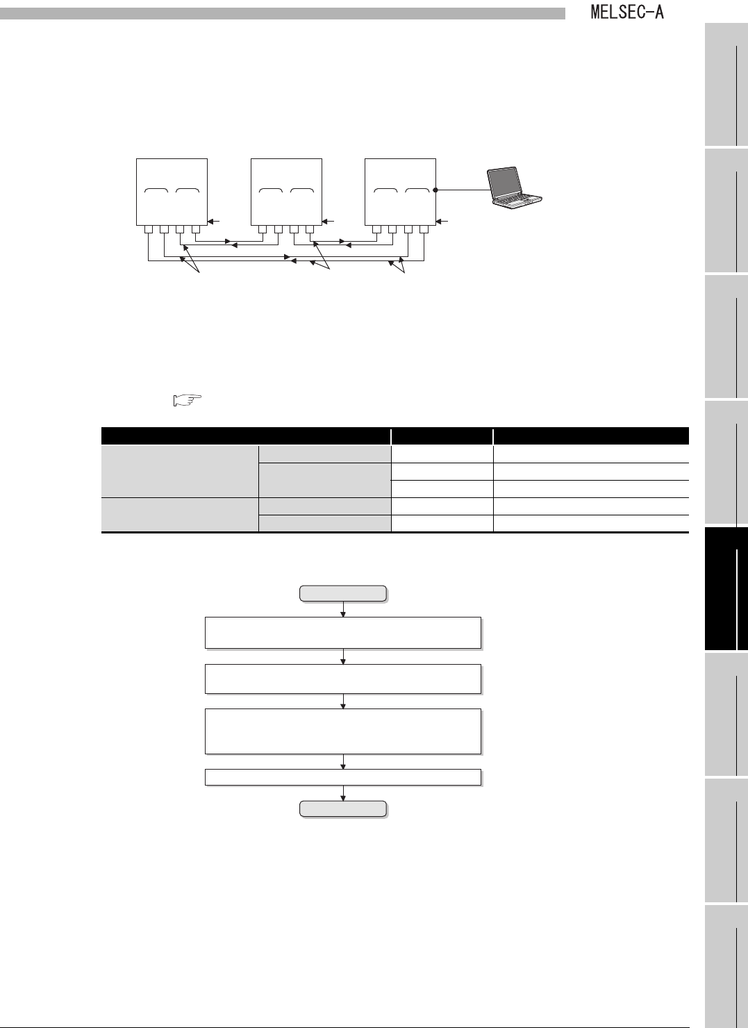
(b) MELSECNET(A1SJ71AR23Q)
A coaxial cable connects the OUT and IN of all stations.
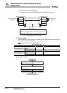
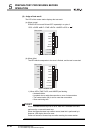
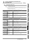
(2) Switch setting
Set the RUN/STOP switch of the CPU module to STOP, and set the DIP switch on the
front of the link module as follows:
( Section 5.3 Part Names and Settings)
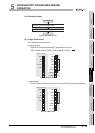
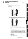
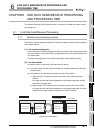
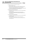
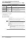
(3) Execution of test
Figure 5.25 MELSECNET(A1SJ71AR23Q)
Table 5.7 Switch setting
Item No. (Set value) Description
Master station
Station No. setting switch 00 Station No.0
Mode setting switch
3 Forward loop test
4 Reverse loop test
Slave stations No.1 and No.2
(Local stations No.1 and No.2)
Station No. setting switch 01, 02 Station No.1 and 2
Mode setting switch 0 Online (with automatic return function)
Figure 5.26 Execution of test
Master station
Station No.02
Front Front Front
R-RD
F-SD
F-RD
R-SD
IN
OUT
R-RD
F-SD
F-RD
R-SD
INOUT
R-RD
F-SD
F-RD
R-SD
INOUT
Local station
No.1
Station No.01 Station No.00
Data flow of
forward loop
Data flow of
reverse loop
Coaxial cable
GX Developer
Local station
No.2
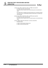
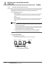
Start
End
Judge the test result.
Put Q series local station into the RUN status
(Y10=ON).
Turn ON from OFF the power supply of a slave
station or reset the CPU module.
Turning ON from OFF the power supply of the master
station or resetting the CPU module leads to start the
test.