


5 - 17
5.5 Self-diagnostic Test
5.5.2 Station-to-station test
5
PREPARATORY PROCEDURES BEFORE
OPERATION
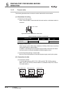
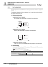
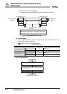
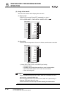
(c) MELSECNET/B(A1SJ71AT23BQ)
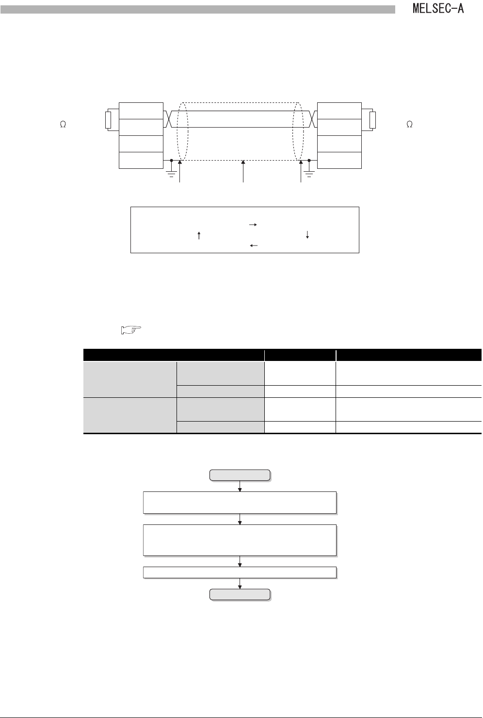
The connection of the MELSECNET/B(A1SJ71AT23BQ) is as follows:
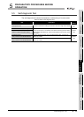
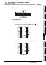
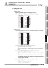
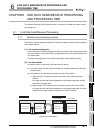
(2) Switch setting
Set the RUN/STOP switch of the CPU module to STOP, and set the DIP switch on the
front of the link module as follows:
( Section 5.3 Part Names and Settings)
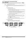
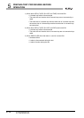
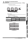
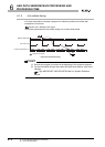
(3) Execution of test
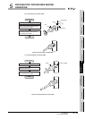
Figure 5.20 MELSECNET/B(A1SJ71AT23BQ)
Table 5.6 Switch setting
Item No. (Set value) Description
Executing station No. n
Station No. setting
switch
01 Station No.1
Mode setting switch 5 Station-to-station test (Executing station)
Other station No. n + 1
Station No. setting
switch
02 Station No.2
Mode setting switch 6 Station-to-station test (Other station)
Figure 5.21 Execution of test
SDA/RDA
SDB/RDB
SG(L)
FG
SDA/RDA
SDB/RDB
SG(L)
FG
Shielded twisted
pair cable
Shield Shield
Data flow
Executing station No.n Other station No.n+1
SDA/SDB of executing station RDA/RDB of other station
RDA/RDB of executing station SDA/SDB of other station
Terminating resistor
(110 1/2W)
Terminating resistor
(110 1/2W)
Start
End
Judge the test result.
Turn ON from OFF the power supply of the other
station or reset the CPU module.
Turning ON from OFF the power supply of the
executing station No.n or resetting the CPU module
leads to start the test.