


5
PREPARATORY PROCEDURES BEFORE
OPERATION
5.5 Self-diagnostic Test
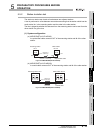
5.5.2 Station-to-station test
5 - 18
1
OVERVIEW
2
SYSTEM
CONFIGURATION
3
SPECIFICATIONS
4
FUNCTIONS
5
PREPARATORY
PROCEDURES BEFORE
OPERATION
6
LINK DATA SEND/
RECEIVE PROCESSING
AND PROCESSING TIME
7
PROGRAMMING
8
TROUBLESHOOTING
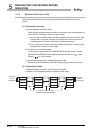
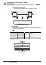
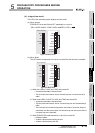
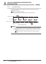
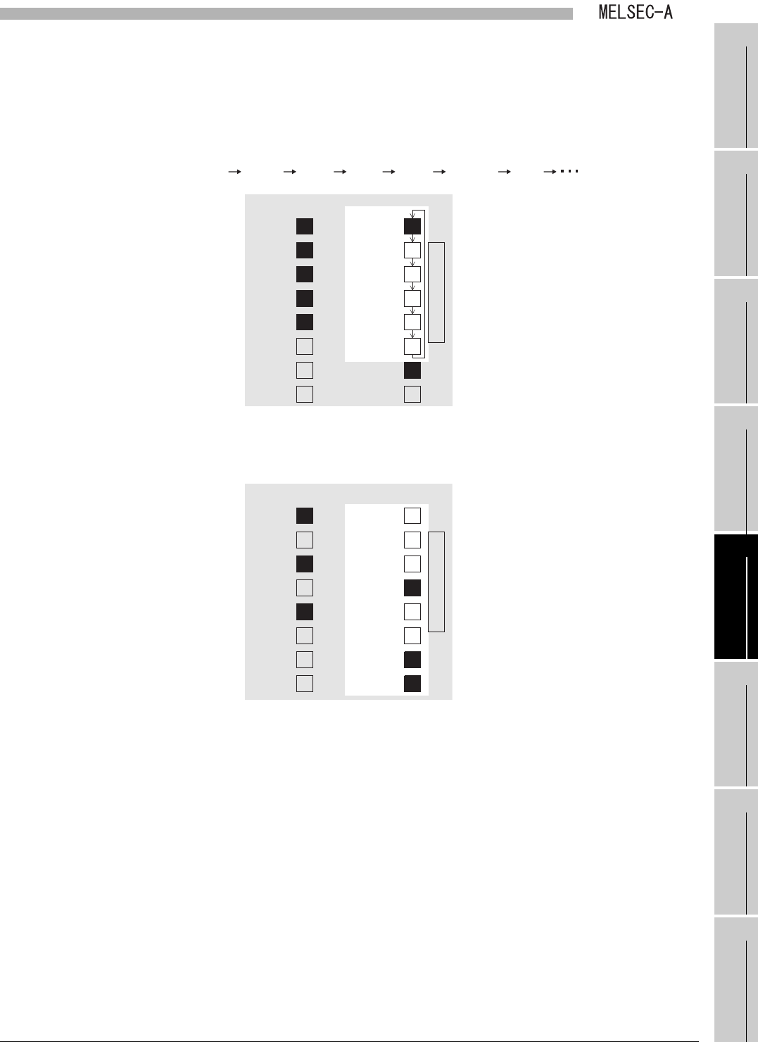
(4) Judge of test result
The LED of the executing station displays the test result.
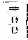
(a) When normal
ERROR LED is turned ON and OFF repeatedly in a cycle of
"CRC OVER AB.IF TIME DATA UNDER CRC ".
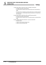
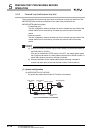
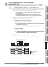
(b) When failed
The LED which corresponds to the error is turned ON, and the test is canceled.
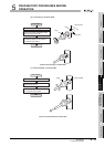
1) When two LEDs (F.LOOP and TIME) are turned ON
• A forward loop cable is disconnected
• The send side and receive side of forward loop are not connected by a
cable
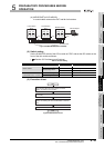
2) When three LEDs (F.LOOP, R.LOOP, and TIME) are turned ON
• A reverse loop cable is disconnected
• The send side and receive side of a reverse loop are not connected by a
cable
• The send side of a forward loop and the send side of a reverse loop are
connected, and the receive side of a forward loop and the receive side of
a reverse loop are connected.
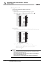
3) When ERROR LED other than above 1) and 2) is turned ON
• Hardware failure
• A cable is disconnected during the test
• A cable is broken during the test
Figure 5.22 When normal
Figure 5.23 When failed
A
1SJ71AP23Q
E
R
R
O
R
RUN
SD
RD
F.LOOP
CPU
CRC
OVER
AB.IF
TIME
DATA
UNDER
F.LOOP
R.LOOP
A
1SJ71AP23Q
RUN
SD
RD
F.LOOP
CPU
CRC
OVER
AB.IF
TIME
DATA
UNDER
F.LOOP
R.LOOP
E
R
R
O
R