


3 - 11
3.4 I/O Signal for Programmable Controller CPU
3.4.1 List of I/O signal
3
SPECIFICATIONS
3.4 I/O Signal for Programmable Controller CPU
3.4.1 List of I/O signal
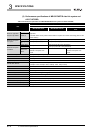
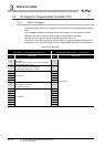
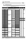
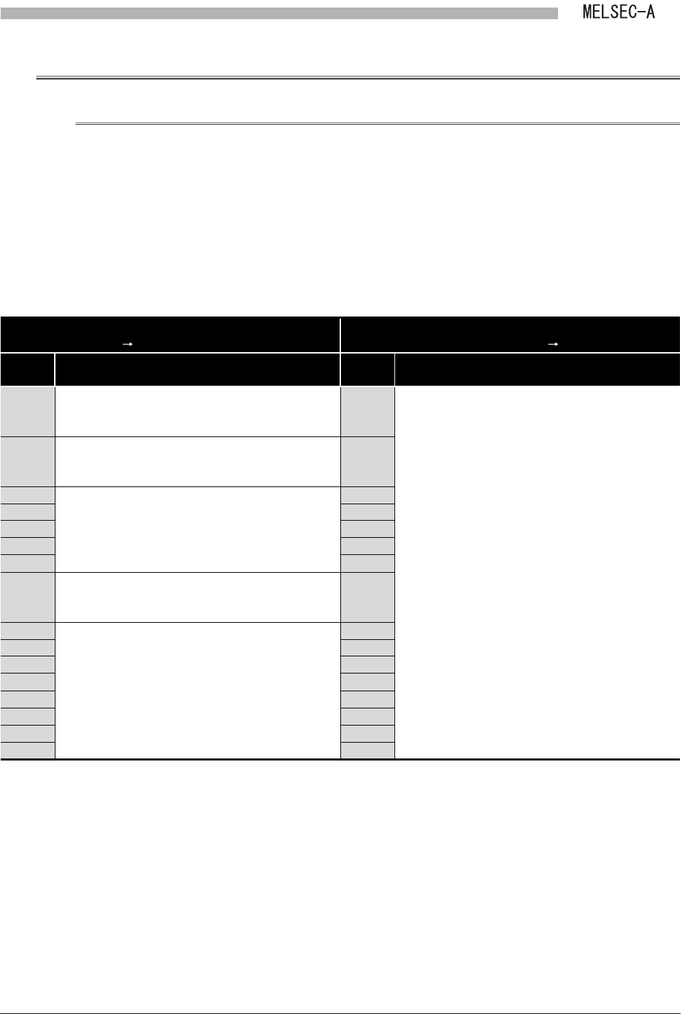
The following shows the list of I/O signal of a local module to the programmable controller
CPU.
The I/O signal is assigned, assuming that start I/O number of a local module is "0000".
Replace it with the I/O signal of a slot where the local module is mounted.
Note that a local module cannot be mounted to the main base unit.
The device X is an input signal from a local module to the programmable controller CPU,
and the device Y is an output signal from the programmable controller to a local module.
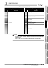
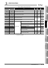
Table 3.9 List of I/O signal
Signal direction
Local module Programmable controller CPU
Signal direction
Programmable controller CPU Local module
Device
No.
Signal name
Device
No.
Signal name
X0
Link status
OFF: Online
ON: Offline, station-to-station test, or self-loopback test
Y0
Use prohibited
X1
B/W initial value setting status
OFF: B/W initial value setting completed
ON: B/W initial value setting in execution
Y1
X2
Use prohibited
Y2
X3 Y3
X4 Y4
X5 Y5
X6 Y6
X7
Refresh ready status
OFF: refresh not requested
ON: Refresh requested
Y7
X8
Use prohibited
Y8
X9 Y9
XA YA
XB YB
XC YC
XD YD
XE YE
XF YF