


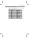


Communications Cable Pin Definitions ––––––––––––––––––––––––
The printer has an 8 pin mini-DIN RS-232C locking connector
with the following pin definitions.
Pin Signal Direction
1 CTS from host
2 RTS from printer
3 TXD from printer
4 GND GND
5 RXD from host
6 DTR from printer
7 DSR from host
8 +5 Volts from printer
Chapter 7. Specifications
7-3