9820/9830/9835 Service Manual Functional Description
10 TC9830SM Rev. B 7/98 Confidential July 1998
RS-232 interface
This interface allows connection to devices capable of
RS-232 communications. The interface is incorporated
in the microcontroller and has DIP switches to set
communications parameters. The DIP switches can
be set manually by the user or through software
control.
Centronics IEEE-1284 Parallel Interface
This interface accommodates high data rates, up to
2M Bits/Second.
IEEE 1284 Bi-Directional Parallel Interface
An IEEE 1284 High Speed Bi-directional Parallel
interface provides parallel communications. The
microcontroller directly controls the port. The
interface allows compatibility with the Centronics
interface as well as allowing for High Speed Bi-
directional communications.
NOTE: Third party LAN devices are connected
through the parallel interface to allow the
printer to interface different LAN networks.
Contrast Control
A manual contrast control, located at the edge of the
Control Board Assy., extends out of the rear cover. It
is used for fine adjustments to the print contrast
values.
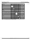
Hardware Power-up Settings (DIPS)
Two 8-switch DIP switches, located on the back panel
of the printer above the contrast adjustment, control
the default power-up configuration of the printer.
Settings include the serial port settings, diagnostics,
ribbon setup, printer mode and supply type.
Peel Module Assembly
The peel module separates the supply from the
backing paper. It consists of an on-demand sensor,
rollers, and a 12Vdc motor drive. Dip SW1 (switch 2)
located on the daughter board enables and disables
the peel function.
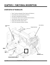
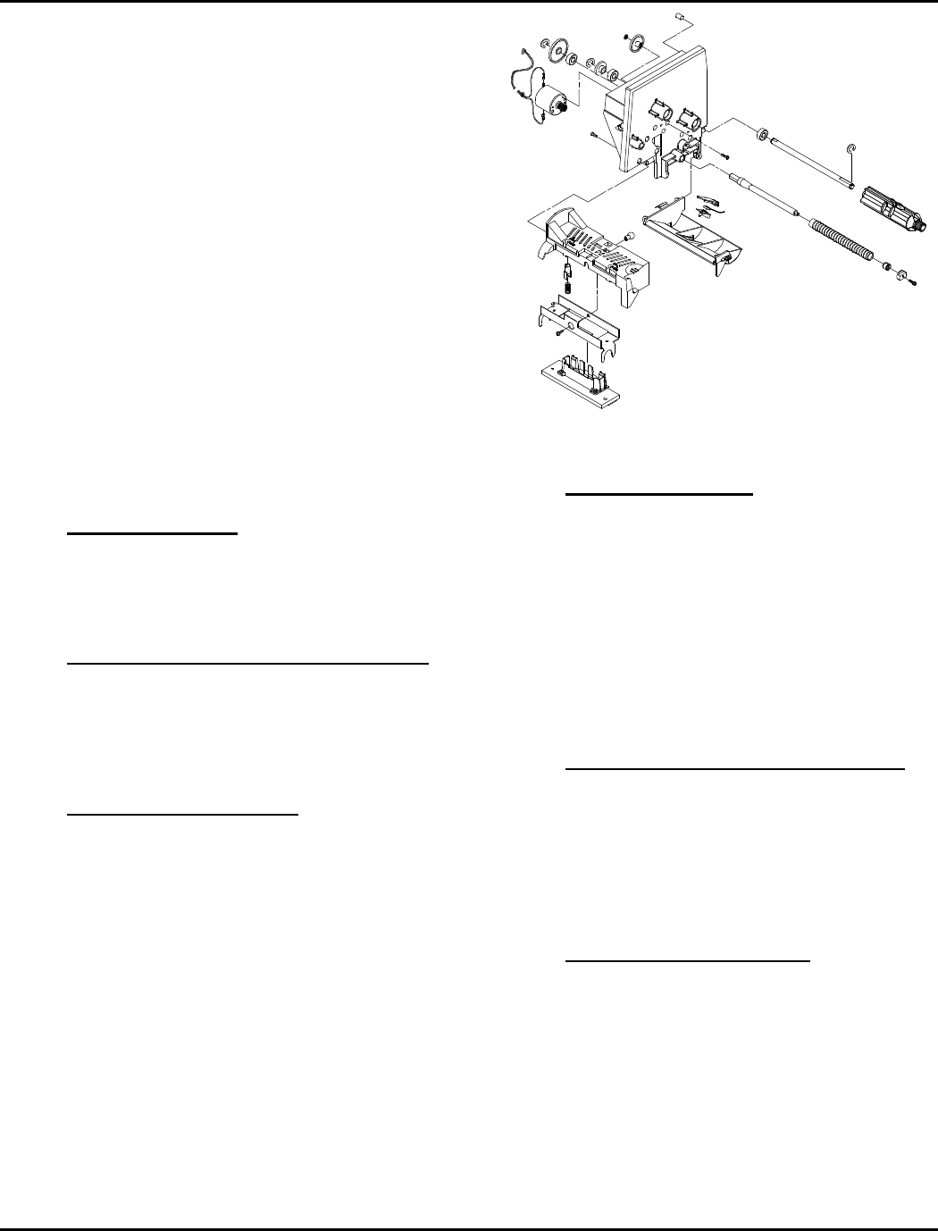
PRINT ASSEMBLY
This Print Module is a plastic casting located inside
the printer’s hood. It is attached to the mid frame by
two bearing blocks which capture studs on the module
back plate. Components of the Print Module are:
Figure 2- 1. Print Assembly
Thermal Printhead
The printhead is located at the bottom front of the
module. It is held in place by a plastic carrier which
acts as an interlock to a formed metal bracket. The
bracket is center-mounted and pivots to ensure an
even pressure on the supply. The printhead bracket
has two alignment loops which slip over the platen
roller to assure dot row to platen roller alignment. The
printhead mount also has two spring loaded
adjustment knobs to adjust printhead pressure for
wide or narrow supplies. A 30 pin ribbon cable
connects the printhead to the Control Board Assy
Ribbon Supply & Take-up Spools
The ribbon supply and ribbon take-up spools are
located on the supply side of the module. Each spool
shaft extends through the module wall and connects to
its own DC drive motor. The spools are designed to
handle a detented ribbon core so when ribbons of
various widths are installed they maintain center
justification.
Ribbon Transfer Rollers
Two ribbon transfer rollers are located on the supply
side of the module. The rollers are ribbed and
attached to metal shafts by retainer screws. One sits
at the very front of the module wall above the
printhead while the other is positioned just above the
supply deflector.


