9820/9830/9835 Service Manual Service Procedures
30 TC9830SM Rev. B 7/98 Confidential July 1998
• ribbon motors and print assembly.
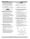
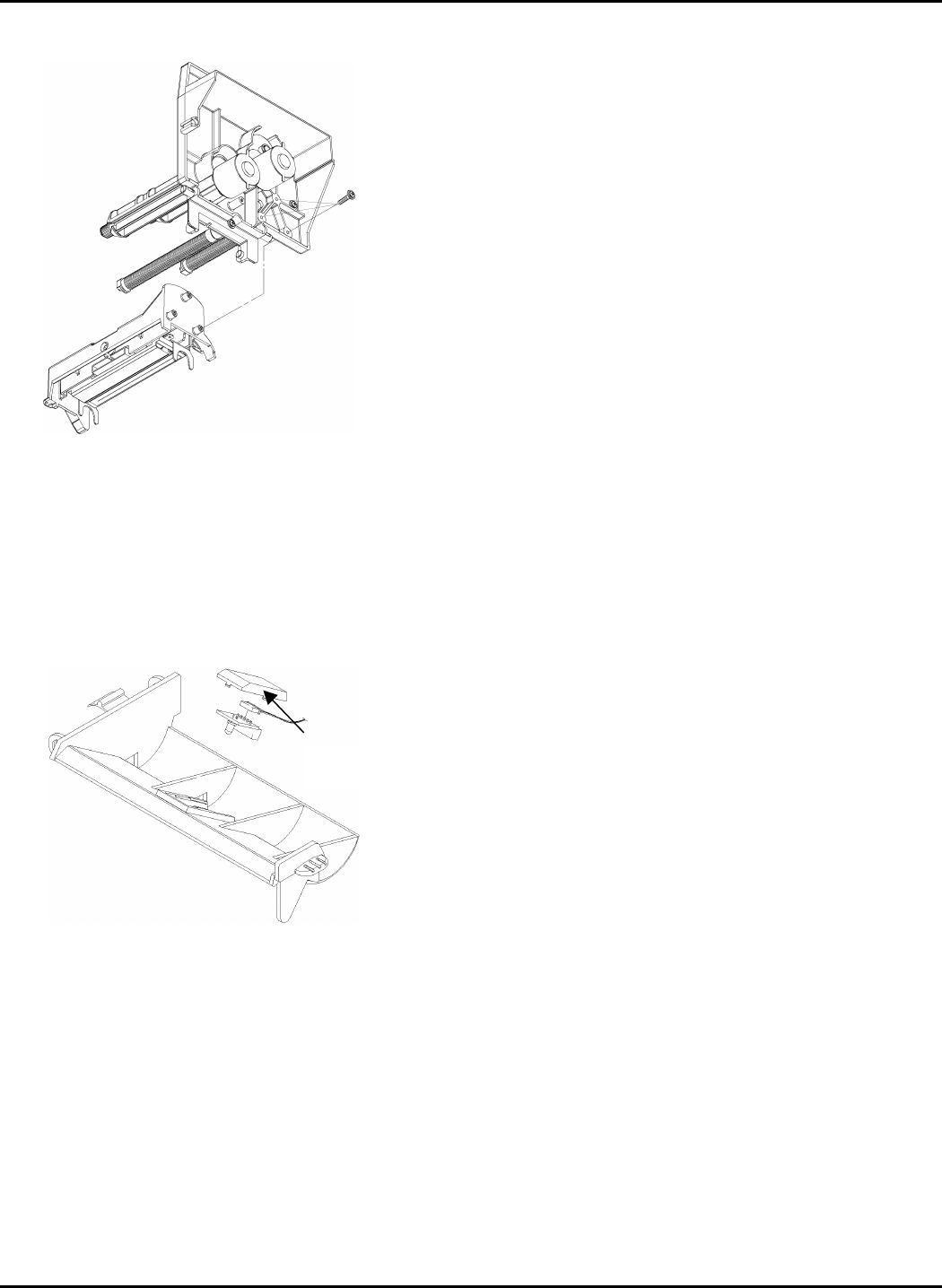
Figure 6-4. Print Assembly
TOOLS/MATERIALS REQUIRED:
• Phillips Screwdriver
• Flat-head Screwdriver
• Ribbon spool intermediate gear retaining clip.
Bi-Cell Emitter Removal
Figure 6-5. Bi-Cell Emitter Removal
1. Using fingers, release emitter cover from the
emitter housing. Slide the emitter out of the
housing. See Figure 6-5.
2. Remove the connector from the sensor circuit
board.
3. Carefully work the sensor harness through the
upper supply guide openings and through the
print assembly opening.
4. Lay the sensor circuit board and harness aside.
Upper Supply Guide Removal
1. Remove bi-cell emitter from the upper supply
guide.
2. Gently pry the supply guide from the pin and
remove it.
Printhead Module Removal
1. Remove the printhead ribbon cable connector at
the printhead end.
2. Remove three printhead module screws, as
shown in Figure 6-4.
3. Remove the printhead module and lay it aside to
prevent it from being damaged.
4. Carefully work the printhead cable back through
the exposed cable slot, and lay it aside.
Ribbon Spool Assembly Removal
1. Remove the C clip at the outer shaft end.
2. Slide spindle off shaft.
3. Reassemble in reverse order.
Ribbon Roller Assembly Removal
1. Remove the screw at the end of the roller shaft.
2. Slide the serrated roller and eccentric adjuster off
the end of the shaft.
3. Reassemble in reverse order.
4. Adjust ribbon tension. See Chapter 5.
DC Ribbon Motor Removal
1. Locate the two patterns of three recessed screws
on the front side of the print module casting.
2. Mark each motor so they aren’t interchanged
when reassembling.
3. Remove the three screws from each pattern while
holding the ribbon motor so it doesn’t fall.
4. Unplug the single wire from the Control Board
Assy.
Cover Tab


