9820/9830/9835 Service Manual Supply Sensing Systems
TC9830SM Rev. B 7/98 Confidential July 199840
20. Remove gray scale and test printer with
customer’s supplies.
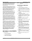
Figure 8- 1. Bi-Cell Sensor Adjustment
NOTE: A hood covers the adjusting screw on the
back of the housing.
REPLACING A SENSOR
Use these instructions for 9835 printers version 5.0 or
earlier. All of the harnesses are identified with part
numbers and must be attached to the sensor board
(118699). Follow the same cable routing that was
used for the original system.
To replace a sensor:
1. Remove the ferrite noise filter from the
old reflective object harness (118704) and install it
on the new harness (118704).
NOTE: Be sure the Reflective Object Sensor is
located in the middle of the sensor
housing (117990)
2. Locate the label that is applied to the top of the
sensor board (118699) and make note of the
Trans and REFL HEX values.
These values must be entered using Sendfile V
2.15. You must convert the HEX value to decimal
using
Microsoft Windows Scientific Calculator.
3. Once the parts have been installed you will need
to power up the printer in Diagnostic Mode. Set
SW-3 on lower
bank of switches to the “ON” position and turn on
the 9835 printer.
4. Start Sendfile and go to the Diagnostics section.
On the left side of the screen you will see a
command that says: Reset 98xx DAC values.
5. Press "R" to enter this function.
6. A pop up menu appears. This is where the
Transmissive (Trans) and Reflective (REFL)
values recorded from the board will be entered.
7. Press 2 followed by the 3-digit decimal value
converted using the scientific calculator.
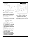
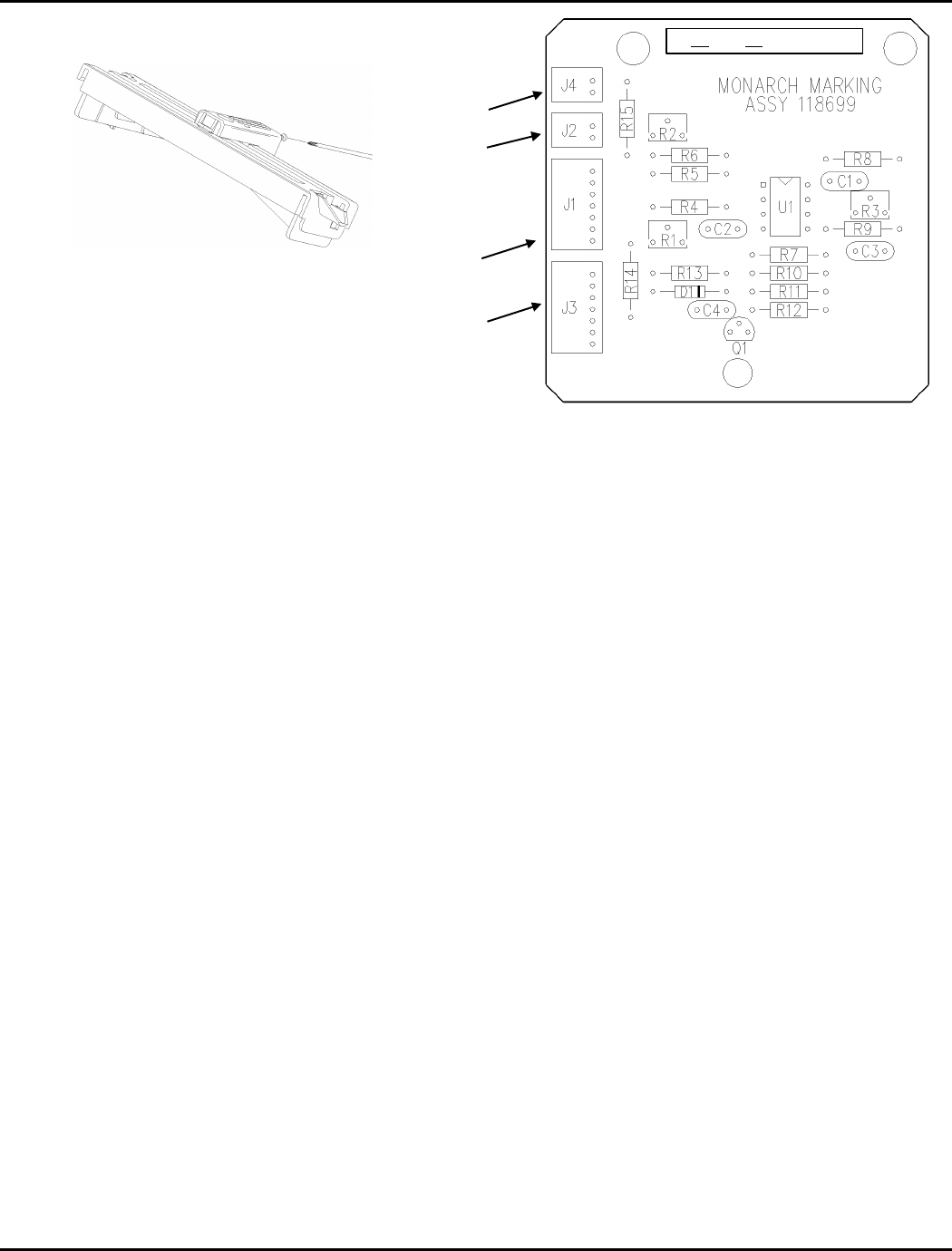
Figure 8- 2. Sensor Board
8. Press 3 followed by the 3-digit decimal value
converted using the scientific calculator. You have
now completed the sensor kit installation.
9. Exit Sendfile and take the printer out of Diagnostic
mode.
10. Test the 9835 using the customers tags or labels
to verify correct operation.
118718
118705
118704
118706
TX 7B RX 8A Ref 4.0


