


2-2 Industio CP-114 User's Manual
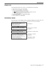
! S2 Data Mode Selection Switch for Port 1/2/3/4:
(Valid if JP5/6 is Left and S1 is ON)
ON* Set the RS-485 port to Automatic Data Direction Control Mode.
OFF Set the RS-485 port to By RTS Mode.
! JP1/2/3/4 Termination Resistor Port 1/2/3/4:
(Valid if JP5/6 is Left and S1 is ON)
Open * Not using Termination Resistor
Short Using Termination Resistor
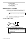
Installing the Industio CP-114 Series Board
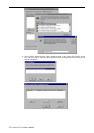
The BIOS automatically assigns the IRQ number and I/O addresses for the Industio CP-114 Series
board. Hence, it is a must to have the board plugged first before installing the software driver. After
this, simply install the control board into the PC and then connect the connection cable.
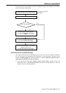
Step 1: Power off the PC.
Warning ! Make sure your system is switched off before you start installing any
board. If you don’t, you may risk damaging your system and the board.
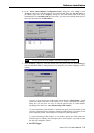
Step 2: Remove the slot cover bracket if present.
Step 3: Plug the Industio CP-114 Series control board firmly into a free 32-bit PCI slot.
Step 4: Fasten the holding screw to fix the control board in place.
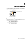
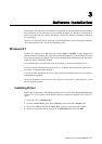
Connecting the Fan-out Cable
Step 5: Connect the fan-out cable (DB37 to DB9 x 4).
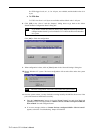
Step 6: Power on the PC and the BIOS will automatically set the IRQ and I/O address.
Note ! Each board must occupy one unique IRQ and four 8-byte I/O addresses,
which are assigned automatically by the BIOS. However, you can select a
free IRQ number manually via the PC’s BIOS setup for the PCI slot, but
normally this method is not available for the I/O address. The possible IRQ
numbers are 2, 3, 4, 5, 7, 10, 11, 12, and 15. The possible I/O addresses are
from 0x0000 to 0xFFFF.
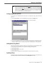
Step 7: Proceed with the software installation detailed in the next chapter, “Software
Installation”.
Fan-out Cable Industio CP-114
JP1
JP2
JP4
JP3
O
N
1 2 3 4
O
N
1 2 3 4
RS-232RS-422
RS-485
JP5
RS-232
RS-422
RS-485
JP6
By RTS RS-422
SW2 SW1
AUTO RS-485