


Connection Cable and Cable Wiring
Industio CP-114 User's Manual 5-7
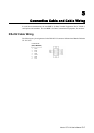
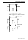
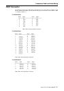
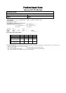
DB37 Connector
The following lists the pin assignments of the Industio CP-114 Series DB37 connector on the
bracket. With this information, you may fabricate any type of fan-out cables, such as DB37 to DB9
x 4 or DB37 to DB25 x 4.
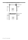
For RS-232 Mode
Pin no. Signal Pin no. Signal
29 RI2 19 TxD1
11 DCD2 30 DTR2
12 GND 31 DSR2
13 CTS2 32 RTS2
14 RxD2 33 TxD2
15 RI1 34 DCD1
16 DTR1 17 DSR1
36 CTS1 18 RTS1
37 RxD1
Note: Make shield grounded to connector.
For RS-422 Mode
Pin no. Signal Pin no. Signal
1 20 CTS2-(A)
2 TxD2-(A) 21 RxD2-(A)
3 GND/VEE2 22 RTS2-(A)
4 CTS2+(B) 23 RTS2+(B)
5 TxD2+(B) 24 RxD2+(B)
6 CTS3-(A) 25 TxD3-(A)
7 RxD3-(A) 26 GND/VEE3
8 RTS3-(A) 27 CTS3+(B)
9 RTS3+(B) 28 TxD3+(B)
10 RxD3+(B) 29 CTS1-(A)
11 TxD1-(A) 30 RxD1-(A)
12 GND/VEE1 31 RTS1-(A)
13 CTS1+(B) 32 RTS1+(B)
14 TxD1+(B) 33 RxD1+(B)
15 CTS0-(A) 34 TxD0-(A)
16 RxD0-(A) 35 GND/VEE0
17 RTS0-(A) 36 CTS0+(B)
18 RTS0+(B) 37 TxD0+(B)
19 RxD0+(B)
Note: Make shield grounded to connector.
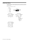
For RS-485 Mode
Pin no. Signal Pin no. Signal
2 Data2-(A) 25 Data3-(A)
3 GND/VEE2 26 GND/VEE3
5 Data2+(B) 28 Data3+(B)
11 Data1-(A) 34 Data0-(A)
12 GND/VEE1 35 GND/VEE0
14 Data1+(B) 37 Data0+(B)
Note: Make shield grounded to connector.