


MultiVOIP User Guide Technical Configuration
105
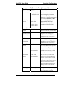
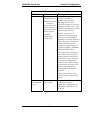
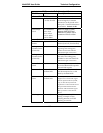
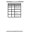
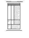
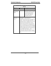
E1 Parameter Definitions (cont’d)
Field Name Values Description
General E1/E1/ISDN Parameters
Line Build Out 0 dB, -7.5 dB,
-15 dB, -22.5 dB
To reduce the crosstalk on
received signals, a transmit
attenuator can be placed in the
data path. Transmit attenuation
is selectable. Default: O dB
Pulse Shape
Level
0 to 40 Meters
40 to 81 m
81 to 122 m
122 to 162 m
162 to 200 m
Refers to length of cable
between MultiVOIP and
PBX/telco in meters. Most
common will be 0 to 40m.
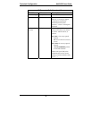
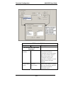
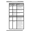
Caller ID Parameters
Caller ID
Enable
Y/N Turns Caller ID feature on (if
checked) and off (if unchecked).
Calling
Number Prefix
(Caller ID)
0-9, *, #
A DTMF symbol used to mark the
beginning of the calling party
number for use with Caller ID.
Maximum length: 4 characters.
Calling
Number Suffix
(Caller ID)
0-9, *, # A DTMF symbol used to mark
the end of the calling party
number for use with Caller ID.
Maximum length: 4 characters.
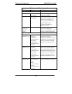
Detect Flash
Hook
Y/N This setting determines whether
or not the MultiVOIP responds
to hook-flash signals.
Detection Time 100 – 1500
milliseconds
Minimum hook-flash time that
will be interpreted as a valid
flash by the MultiVOIP.
Generation
Time
100 – 1500
milliseconds
In some systems, a MultiVOIP
might receive a hook-flash signal
from an upstream device (a PBX,
voip or other device) and must
replicate it to a downstream device.
This parameter determines the
duration of the hook-flash signal
that is passed to a downstream
device.
Clocking External/Internal Set opposite to telco/PBX
setting. Example: if telco
clocking internal, set VOIP
clocking as external.