


MultiVOIP User Guide Mechanical Installation & Cabling
37
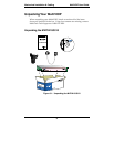
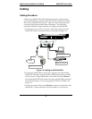
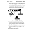
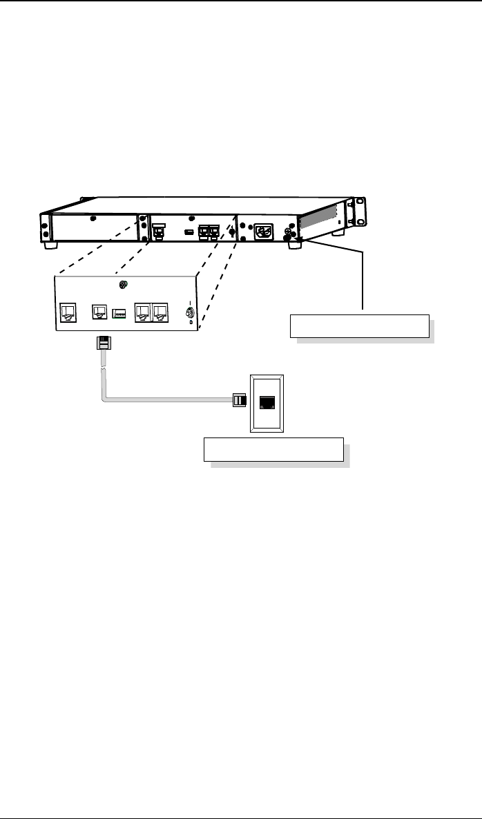
4. If you intend to configure the MultiVOIP remotely using the
MultiVOIP Windows GUI, connect an RJ-11 phone cable between the
Command Modem connector (at the rear of the MultiVOIP) and a
receptacle served by a telco POTS line. See Figure 3-6.
The Command Modem is built into the MultiVOIP unit. To configure
the MultiVOIP remotely using its Windows GUI, you must call into
the MultiVOIP’s Command Modem. Once a connection is made, the
configuration process is identical to local configuration with the
Windows GUI.
ETHERNET COMMAND
DIGITAL VOICE
ETHERN ETCOMMAND
10 BASET
RS232
DIGITA L VO ICE
TRUNK
COMMAND
MODEM
Telco POTS Line
Grounding Screw
Figure 3-6. MVP-2410/3010 Voip Connections
for GND & Remote Config Modem
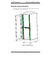
5. Ensure that the unit is properly connected to earth ground by
verifying that it is reliably grounded when mounted within a rack.
This can be accomplished by connecting a grounding wire between
the chassis grounding screw (see Figure 3-6) and a metallic object that
will provide an electrical ground.
6. Turn on power to the MultiVOIP by setting the power switch on the
right side panel to the ON position. Wait for the Boot LED on the
MultiVOIP to go off before proceeding. This may take a couple of
minutes.
Proceed to Chapter 4 “Software Installation.”