


8-Channel Analog Expansion Card MultiVOIP User Guide
362
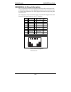
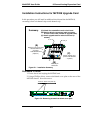
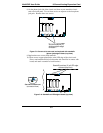
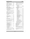
3. Using a Phillips driver, remove the three screws that secure the main circuit
board and back panel assembly to the chassis.
NOTE:
Follow standard ESD
precautions to protect the
circuit board from static
electricity damage.
back panel screws (3)
Figure C-3: Removing screws from back panel
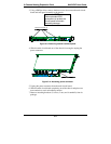
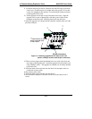
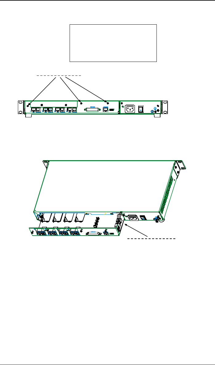
4. Slide the main circuit board out of the chassis far enough to unplug the
power connector.
power connector
Figure C-4: Accessing power connector
5. Unplug the power connector from the main circuit board.
6. Slide the main circuit board completely out of the chassis and place on a
non-conductive, static-safe tabletop surface.
7. Remove mounting hardware (2 screws, 2 nuts, and 4 standoffs) from its
package.