


MultiVOIP User Guide Cable Pinouts
353
Appendix A: Cable Pinouts
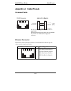
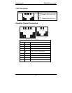
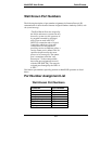
Command Cable
RJ-45 Connector End-to-End Pin Info
1 2 3 4 5 6 7 8
PIN NO.
4
7
8
3
2
6
1
5
1
2
3
4
5
6
7
8
To DTE
Device
(e.g., PC)
CLEAR TO SEND
TRANSMIT DATA
RECEIVE DATA
SIGNAL GROUND
PIN NO.
To Command
Port Connector
DB9FRJ-45
RJ-45 connector plugs into Command Port of
MultiVOIP.
DB-9 connector plugs into serial port of command
PC (which runs MultiVOIP configuration
software).
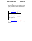
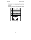
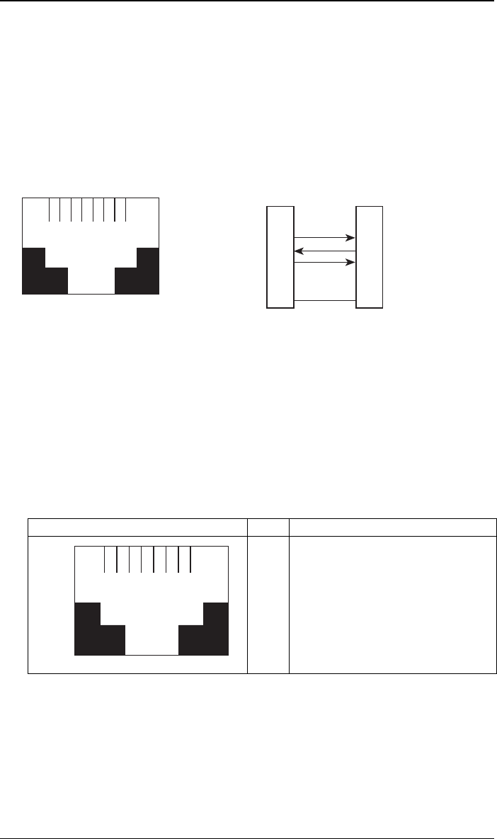
Ethernet Connector
The functions of the individual conductors of the MultiVOIP’s Ethernet port are
shown on a pin-by-pin basis below.
RJ-45 Ethernet Connector Pin Circuit Signal Name
1 2 3 4 5 6 7 8
1
2
3
6
TD+ Data Transmit Positive
TD- Data Transmit Negative
RD+ Data Receive Positive
RD- Data Receive Negative