Chapter 4 – SocketModem Parallel Interface – A Programmer's Description
Multi-Tech Systems, Inc. SocketModem MT5600SMI Developer’s Guide 20
Register Signal Definitions
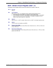
IER – Interrupt Enable Register (Addr = 1, DLAB = 0)
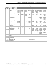
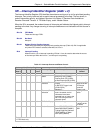
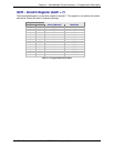
The IER enables five types of interrupts that can separately assert the HINT output signal (Table 4–
2.). A selected interrupt can be enabled by setting the corresponding enable bit to a 1, or disabled by
setting the corresponding enable bit to a 0. Disabling an interrupt in the IER prohibits setting the
corresponding indication in the IIR and assertion of HINT. Disabling all interrupts (resetting IER0 –
IER3 to a 0) inhibits setting of any Interrupt Identifier Register (IIR) bits and inhibits assertion of the
HINT output. All other system functions operate normally, including the setting of the Line Status
Register (LSR) and the Modem Status Register (MSR).
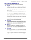
The IER enables five types of interrupts that can separately assert the HINT output signal. A selected
interrupt can be enabled by setting the corresponding enable bit to a 1, or disabled by setting the
corresponding enable bit to a 0. Disabling an interrupt in the IER prohibits setting the corresponding
indication in the IIR and assertion of HINT. Disabling all interrupts (resetting IER0 - IER3 to a 0)
inhibits setting of any Interrupt Identifier Register (IIR) bits and inhibits assertion of the HINT output.
All other system functions operate normally, including the setting of the Line Status Register (LSR)
and the Modem Status Register (MSR).
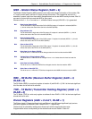
Bits 7-4 Not used.
Always 0.
Bit 3 Enable Modem Status Interrupt (EDSSI).
This bit, when a 1, enables assertion of the HINT output whenever the Delta CTS
(MSR0), Delta DSR (MSR1), Delta TER (MSR2), or Delta DCD (MSR3) bit in the
Modem Status Register (MSR) is a 1. This bit, when a 0, disables assertion of
HINT due to setting of any of these four MSR bits.
Bit 2 Enable Receiver Line Status Interrupt (ELSI).
This bit, when a 1, enables assertion of the HINT output whenever the Overrun
Error (LSR1), Parity Error (LSR2), Framing Error (LSR3), or Break Interrupt
(LSR4) receiver status bit in the Line Status Register (LSR) changes state. This
bit, when a 0, disables assertion of HINT due to change of the receiver LSR bits
1-4.
Bit 1 Enable Transmitter Holding Register Empty Interrupt (ETBEI).
This bit, when a 1, enables assertion of the HINT output when the Transmitter
Empty bit in the Line Status Register (LSR5) is a 1. This bit, when a 0, disables
assertion of HINT due to LSR5.
Bit 0 Enable Receiver Data Available Interrupt (ERBFI) and Character Timeout in
FIFO Mode.
This bit, when a 1, enables assertion of the HINT output when the Receiver Data
Ready bit in the Line Status Register (LSR0) is a1 or character timeout occurs in
the FIFO mode. This bit, when a 0, disables assertion of HINT due to the LSR0
or character timeout.


