


Chapter 5 – AT Commands, S-Registers, and Result Codes
Multi-Tech Systems, Inc. SocketModem MT5600SMI Developer’s Guide 66
Unless otherwise noted, all values are hexadecimal numbers. Any numeric
values from tables in ITU V.58 are converted to hexadecimal. Multi-digit
values are reported MSD first. Leading 0’s may be deleted. See examples
in Table 5-13.
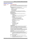
Monitoring an Active Connection
This command is intended for use after call termination. However, codes are
defined so that a modem can respond before the first call is placed, and during a
call for live monitoring purposes. For example, key 60, call termination, has value
1 defined, indicating that the call is still in progress.
There are at least two ways to do this. First, the DTE could switch the modem to
Online command state, issue the command, capture the responses and then
issue an ATO command. For smoother online monitoring, in-band means defined
in ITU V.80 are recommended if available in the modem. If V.80 methods are
used, each response line shall be a separate extended in-band message.
Notes for Tables
1. The modem may insert a delay (e.g., 10 ms) between information text lines.
2. The code tables include values for data and fax calls. Some of the codes are
applicable only to data calls (e.g., data compression), some are applicable
only to call origination (e.g., busy, answering signal detection) and some are
applicable only to the answering modem (e.g., calling signal detection).
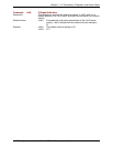
callCleared codes from 3.6.4/V.58-1994
callCleared: indicates that the DCE has gone on-hook and that the previously
existing network connection has been cleared. These values are hex values,
converted from decimal in V.58. callCleared codes are described in Table 5-12.
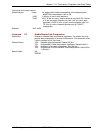
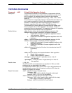
Table 5-4. AT#UD Last Call Status Report Format
Key Value(s) Definition
0 2 digits Diagnostic Command Specification revision number, digit.digit
1 Table 5-5 Call Setup Result code
2 Table 5-6 Multi-media mode
3 Table 5-7 DTE-DCE interface mode
4 String V.8 CM octet string, same format as V.250, in quotes
5 String V.8 JM octet string, same format as V.250, in quotes
10 0-2F Received signal power level, in –dBm (0-43)
11 0-1F Transmit signal power level, in –dBm (e.g., 0-17)
12 0-64 Estimated noise level, in –dBm (e.g., 10-90)
17 0-FFF Round Trip delay, in units of ms
18 Table 5-8 V.34 INFO bit map
20 Table 5-9 Transmit Carrier Negotiation Result
21 Table 5-9 Receive Carrier Negotiation Result
22 0-1F40 Transmit Carrier symbol rate (0-8000) in symbol/s
23 0-1F40 Receive Carrier symbol rate (0-8000) in symbol/s
24 0-FA0 Transmit Carrier frequency (0-4000) in Hz
25 0-FA0 Receive Carrier frequency (0-4000) in Hz
26 0-FA00 Initial transmit carrier data rate (0-64000) in bit/s
27 0-FA00 Initial receive carrier data rate (0-64000) in bit/s
30 0-FF Temporary carrier loss event count
31 0-FF Carrier Rate re-negotiation event count
32 0-FF Carrier Retrains requested
33 0-FF Carrier Retrain requests granted
34 0-FA00 Final transmit carrier data rate in bit/s
35 0-FA00 Final receive carrier data rate in bit/s
40 Table 5-10 Protocol Negotiation Result
41 0-400 Error Control frame size in bytes
42 0-FF Error control link timeouts in transmission
43 0-FF Error control link NAKs received
44 Table 5-11 Compression Negotiation Result
50 0-2 Transmit flow control: 0=off; 1=DC1/DC3; 2=V.24 circuit 106/133
51 0-2 Receive flow control: 0=off; 1=DC1/DC3; 2=V.24 circuit 106/133
52 0-FFFFFFFF Transmit characters sent from DTE
53 0-FFFFFFFF Received characters sent to DTE
54 0-FFFF Transmit characters lost (data overrun errors from DTE)