


MultiVOIP User Guide Mechanical Installation & Cabling
73
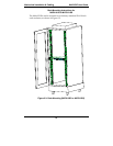
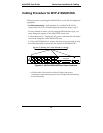
8. Ensure that the unit is properly connected to earth ground by
verifying that it is reliably grounded when mounted within a rack.
This can be accomplished by connecting a grounding wire between
the chassis grounding screw (see Figure 3-9) and a metallic object that
will provide an electrical ground.
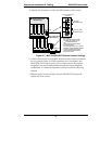
9. Turn on power to the MultiVOIP by placing the ON/OFF switch on
the back panel to the ON position. Wait for the Boot LED on the
MultiVOIP to go off before proceeding. This may take a few minutes.
Proceed to Chapter 4 to load the MultiVOIP software.
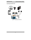
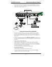
Cabling Procedure for MVP210-SS
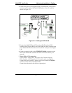
Cabling involves connecting the MultiVOIP to your LAN and telephone
equipment.
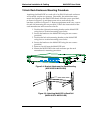
1.
For DID channels only. If both channels of your MVP210-SS
MultiVOIP will be using either FXS, FXO, or E&M telephony
interfaces, skip to step 2.
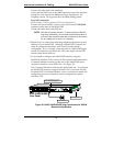
For any channel on which you are using the DID interface type, you
must change the jumper on the MultiVOIP circuit card.
a. Disconnect power. Unplug the AC power cord from the wall outlet
or from the receptacle on the MultiVOIP unit.
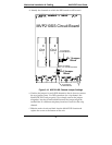
b. Using a #1 Phillips driver, remove the screw (at bottom of unit,
near the back-cover end) that attaches the main circuit card to the
chassis of the MVP210-SS.
c. Pull the main circuit card out about half way.