


Mechanical Installation & Cabling MultiVOIP User Guide
74
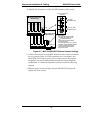
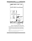
d. Identify the channels on which the DID interface will be used.
J3
J7
J9J5
J11
FB3
LED2
R72
J1
S10
R113
R114
LED12
J15
LED7
LED11 LED10
LED14
LED 5 LED 3 LED1
R58 R2R57
LED6 LED4LED 9
R56
R74
R205
LED13
R55
LED8
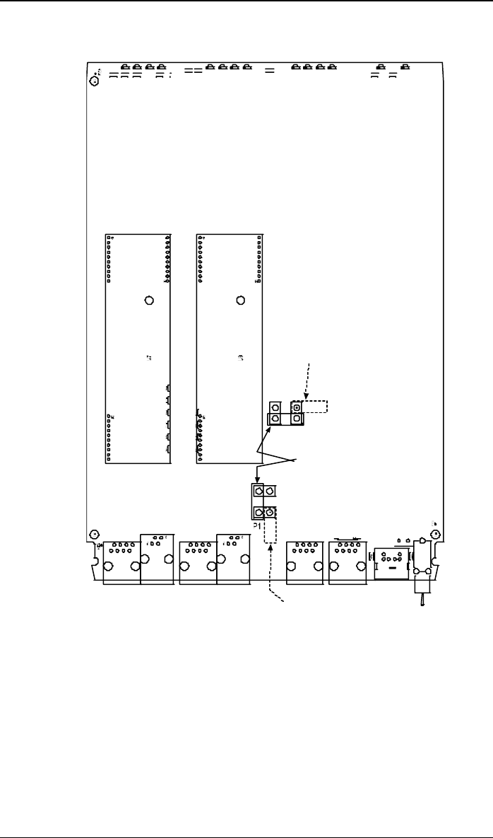
Ch1
Ch2
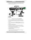
Ch 2 Jumper
Block
MVP210SS Circuit Board
JP1
JP8
as configured
for DID Interface
as shipped,
for non-DID interfaces
Ch 1 Jumper
Block
JP7
JP4
as configured
for DID Interface
P7
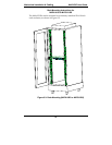
Figure 3-10. MVP210-SS Channel Jumper Settings
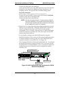
e. Position the jumper for each DID channel so that it does not connect
the two jumper posts. For DID operation of a voip channel, the
MultiVOIP will work properly if you simply remove the jumper
altogether, but that is inadviseable because the jumper might be
needed later if a different telephony interface is used for that voip
channel.
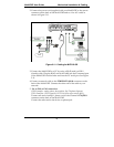
f. Slide the main circuit card back into the MultiVOIP chassis and
replace the screw at the bottom of the unit.