


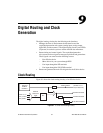

Chapter 9 Digital Routing and Clock Generation
© National Instruments Corporation 9-5 NI 6124/6154 User Manual
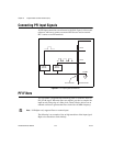
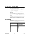
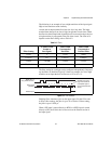
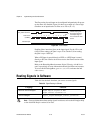
Figure 9-2. S Series PCI Device RTSI Pinout
Using RTSI as Outputs
RTSI <0..7> are bidirectional terminals. As an output, you can drive any of
the following signals to any RTSI terminal:
• AI Start Trigger (ai/StartTrigger)
• AI Reference Trigger (ai/ReferenceTrigger)
• AI Convert Clock* (ai/ConvertClock)
• AI Sample Clock (ai/SampleClock)
• AO Sample Clock* (ao/SampleClock)
• AO Start Trigger (ao/StartTrigger)
• AO Pause Trigger (ao/PauseTrigger)
• 10 MHz Reference Clock
32 RTSI 6
34 RTSI 7
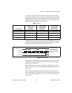
Table 9-1. RTSI Signals (Continued)
Terminal RTSI Bus Signal
Ter m in al 2
T
erm
i
na
l
34
Ter m in al 33
Ter m in al 1