


Chapter 5 Analog Output
NI 6124/6154 User Manual 5-8 ni.com
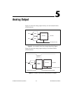
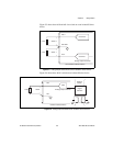
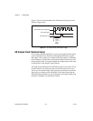
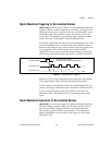
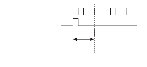
Figure 5-7 shows the relationship of the AO Sample Clock signal to the
AO Start Trigger signal.
Figure 5-7. AO Sample Clock and AO Start Trigger
AO Sample Clock Timebase Signal
You can select any PFI or RTSI pin as well as many other internal signals
as the AO Sample Clock Timebase (ao/SampleClockTimebase) signal.
This signal is not available as an output on the I/O connector. AO Sample
Clock Timebase is divided down to provide the Onboard Clock source for
the AO Sample Clock. You specify whether the samples begin on the rising
or falling edge of AO Sample Clock Timebase.
You might use the AO Sample Clock Timebase signal if you want to use an
external sample clock signal, but need to divide the signal down. If you
want to use an external sample clock signal, but do not need to divide the
signal, then you should use the AO Sample Clock signal rather than the
AO Sample Clock Timebase. If you do not specify an external sample clock
timebase, NI-DAQmx uses the Onboard Clock.
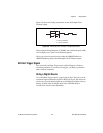
AO Start Trigger
AO Sample Clock
AO Sample Clock Timebase
Delay
From
Start
Trigger